Examples for digital configuration
An area should be monitored in which an edge is passing.
1. Define Qx as the switching output.
2. Set Qx to "Qint configuration".
3. Set the mode to “Window mode”.
4. Select the edge to be monitored under “Task”.
5. Enter values for switching point 1/2 which are larger/smaller than the edge posi‐
tion.
✓
As soon as the edge is within the area, the “1” value is output.
10.4.8 "RS-485” menu
The “RS-485” menu is only displayed if the MLG-2 variant is equipped with an RS-485
interface.
You can parameterize the RS-485 interface via the “RS-485” menu.
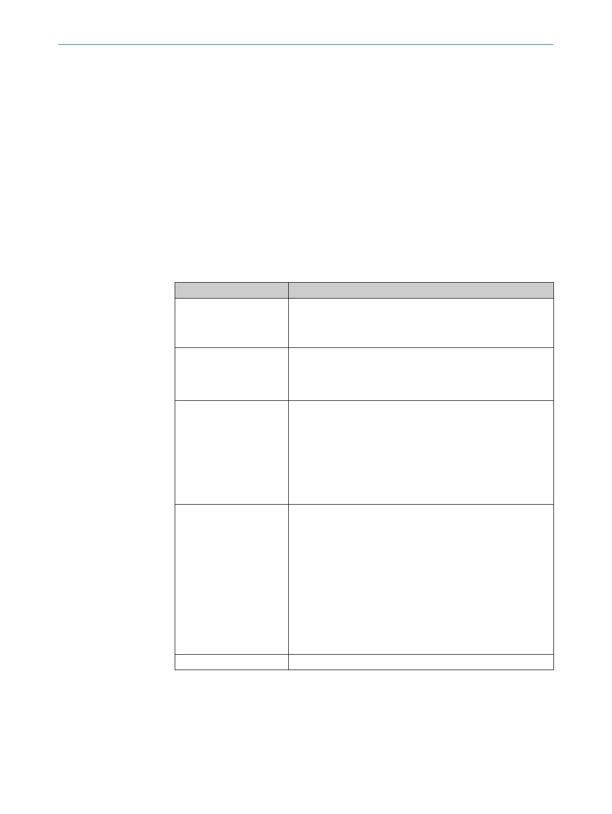
Table 33: RS-485
Designation Description
Baud rate Select baud rate or data transmission rate.
The following baud rates in bit/s are supported: 1200, 2400,
4800, 9600, 19200, 38400, 57600, 115200, 230400, 460800,
500000, 921600
Parity Select option for parity check.
•
No parity check
•
Odd parity
•
Even parity
Format of data interface Parameterize the data point format.
The format is composed as follows:
•
Start character
•
Format of transmission telegram: Hexadecimal, decimal or
binary
•
Separator
•
Up to two stop characters
•
Parity
Report mode Select report mode.
•
Interval (Time_Interval): The data is transmitted in accordance
with the entered interval.
•
Continuous: The data is transmitted constantly.
•
By request (through character reception): The data is transmit‐
ted as soon as and as long as the selected characters are
received.
•
Triggered (through switching input): The data is transmitted as
soon as and as long as the configured signal is pending on the
switching input. The switching input must be parameterized for
this function.
•
Inactive: The RS-485 interface is deactivated, e.g. no data
transmission
Interval (Time_Interval) Enter time for transmission mode in "Interval” in ms.
CONFIGURATION WITH SOPAS 10
8024643/2019-09-02 | SICK O P E R A T I N G I N S T R U C T I O N | MLG-2 WebChecker
77
Subject to change without notice