10.2 “General Device Settings” page
10.2.1 Overview
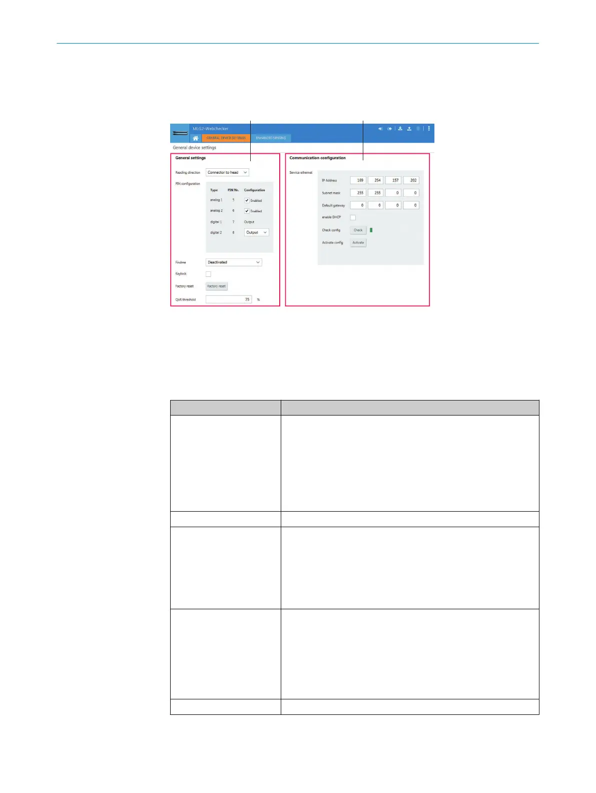
Figure 48: “General Device Settings” page (example)
1
“General settings” area
2
“Communication configuration” area
10.2.2 “General settings” area
Table 26: General settings
Designation Description
Reading direction Set reading direction. This setting determines the edge numbers.
•
Read direction from the connection side of the head side: The
MLG-2 reads from the connection to the head side. The first
detected edge from the connection side contains number E1.
•
Read direction from the head side of the connection side: The
MLG-2 reads from the head to the connection side. The first
detected edge from the head side contains number E1.
Factory setting: Read direction from connection side to head side
PIN configuration See the following “PIN configuration” section.
Device search function If multiple MLG-2 units are installed in one application, you can
identify a certain MLG-2 via IO-Link and the device search func‐
tion.
•
Deactivated: Operational status is displayed via LEDs as usual.
•
Activated: All LEDs flash simultaneously with 1 Hz.
Factory setting: Deactivated
Key lock Activate or deactivate the lock for the Teach pushbutton on the
receiver of the MLG-2.
•
Checkbox activated: Pushbutton lock activated. The MLG-2
cannot be operated via the Teach pushbutton.
•
Checkbox deactivated: Pushbutton lock deactivated. The
MLG-2 is can be operated via the Teach pushbutton.
Factory setting: Pushbutton lock deactivated.
Factory settings Reset MLG-2 to factory setting
CONFIGURATION WITH SOPAS 10
8024643/2019-09-02 | SICK O P E R A T I N G I N S T R U C T I O N | MLG-2 WebChecker
63
Subject to change without notice