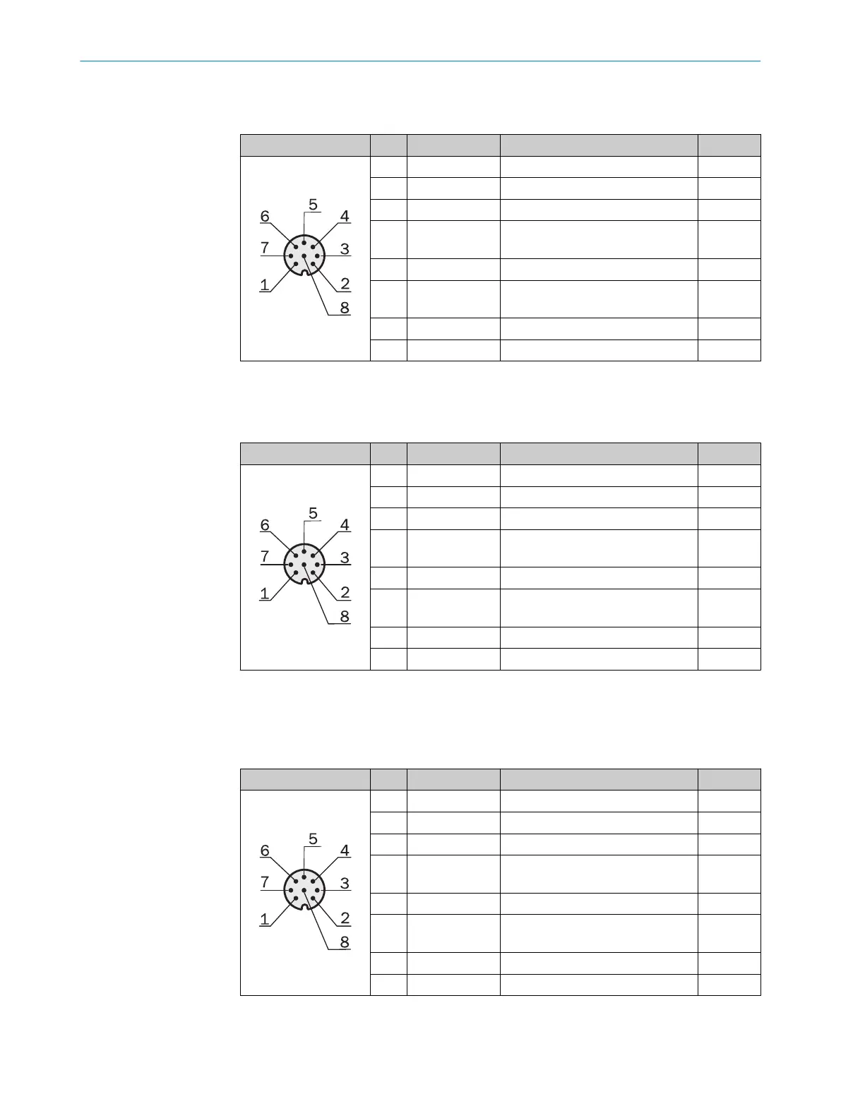
Receiver I/O connection with analog outputs (QA): M12, 8-pin, Acoded
Table 18: Pin assignment, I/O, receiver with 2 x QA
Male connector Pin Signal Meaning Color
1 L+ 24 V supply voltage Brown
2 Sync_A Synchronization White
3 M GND supply voltage Blue
4 Q1 / C Switching output 1 with
IO-Link interface
Black
5 Sync_B Synchronization Gray
6 Q2 / IN1 Switching output 2 or
switching input 1
1
Pink
7 QA1 Analog output 1 Violet
8 QA2 Analog output 2 Orange
1
Configurable
Receiver I/O connection with RS-485 interface: M12, 8-pin, Acoded
Table 19: Pin assignment, I/O, receiver, with RS485
Male connector Pin Signal Meaning Color
1 L+ 24 V supply voltage Brown
2 Sync_A Synchronization White
3 M GND supply voltage Blue
4 Q1 / C Switching output 1 with
IO-Link interface
Black
5 Sync_B Synchronization Gray
6 Q2 / IN1 Switching output 2 or
switching input 1
1
Pink
7 RS485_A RS-485 interface Violet
8 RS485_B RS-485 interface Orange
1
Configurable
Receiver I/O connection with switching outputs and analog output: M12, 8-pin, A‐
coded
Table 20: Pin assignment, I/O, receiver with 3 x Q and 1 x QA
Male connector Pin Signal Meaning Color
1 L+ 24 V supply voltage Brown
2 Sync_A Synchronization White
3 M GND supply voltage Blue
4 Q1 / C Switching output 1 with
IO-Link interface
Black
5 Sync_B Synchronization Gray
6 Q2 / IN1 Switching output 2 or
switching input 1
1
Pink
7 Q3 Switching output 3 Violet
8 QA Analog output Orange
1
Configurable
6 ELECTRICAL INSTALLATION
40
O P E R A T I N G I N S T R U C T I O N | MLG-2 WebChecker 8024643/2019-09-02 | SICK
Subject to change without notice