E3M120 Line module ”CBA8000/TS9000”
105
Building Technologies 001260_k_en_--.doc
Fire Safety & Security Products 02.2005
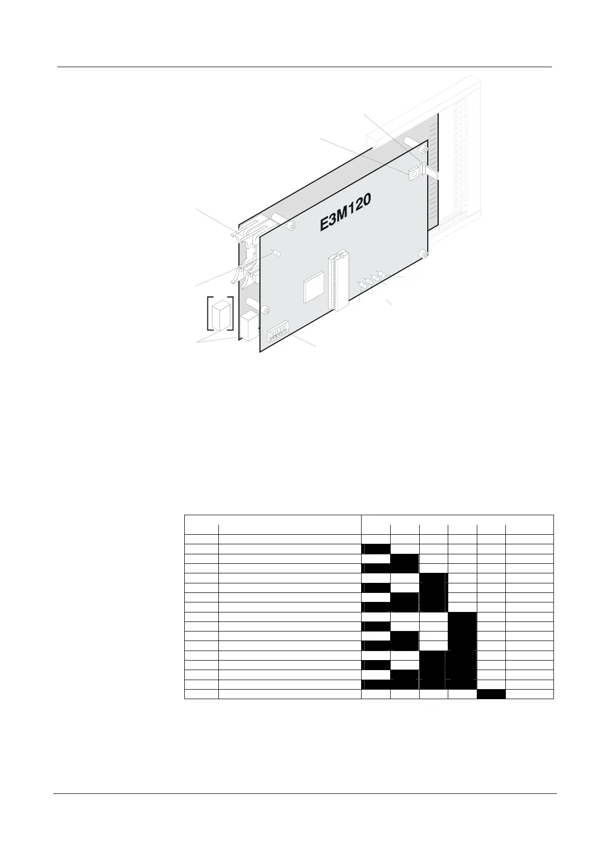
25.4 Important components
1
2
3
4
5
6
7
S2
X1
[ST1]
LD1
ST1
[J1]
µ
P
K1
1
4
1
4
J6
1
ON
S1
LD2
LD3
LD4
LD5
EPROM
Legend:
1 Jumper "X1" [ST1]: 'in' = Watchdog active (factory setting)
'out' = for development only
2 Key "S2": Reset line interface µP (not I-Bus controller)
3 Flat cable header "ST1" [J1] (26-pin): I-Bus
4 LED green "LD1": indicates power ON
5 Plug-in terminals "K1" [J6]: Supply to "I-Bus" modules
6 Programming switch "S1": "I-Bus address" setting
Each element (module) connected to I-Bus must have an individual address (number).
This is set on programming switch "S1".
Maximum 16 I-Bus devices.
Function / I-Bus address Programming switch S1
No. S1-1 S1-2 S1-3 S1-4 S1-5 S1-6
0 Module out of commission (unused) off off off off off off
1 I-Bus user number 1 on off off off off off
2 2 off on off off off off
3 3 on on off off off off
4 4 off off on off off off
5 5 on off on off off off
6 6 off on on off off off
7 7 on on on off off off
8 8 off off off on off off
9 9 on off off on off off
10 10 off on off on off off
11 11 on on off on off off
12 12 off off on on off off
13 13 on off on on off off
14 14 off on on on off off
15 15 on on on on off off
16 16 off off off off on off
"S1-1...6" are set to "off" at the factory
7 LED red "LD2...LD5":
pulsating = Communication between I-Bus and E3M120 ok
continuous = Line reset or line pulled down to 0 V (short circuit)

 Loading...


