E3M171 Line module ”Interactive” Ex Detectors
90
Building Technologies 001260_k_en_--.doc
Fire Safety & Security Products 02.2005
21 E3M171 Line module ”Interactive” Ex Detectors
21.1 Overview
z Line module for interactive Ex detectors (and standard detectors)
z I-Bus module with line processor and independent emergency operation proces-
sor
z Designed for 1 stub line
z Line inputs protected against over voltage
z The ground fault monitoring is disabled, because Ex barrier must be grounded
on the plus conductor
z Line is galvanically isolated from the control unit
z Card format 100 mm x 200 mm
z I-Bus address is set at programming switch ”S3”
21.2 Key data
Addresses ...32 (normal and/or Ex detectors) 1)
Number of wires 2
Twisted cable necessary
Line resistance (total)
...70 Ω 1) 2) 3)
Line capacitance (from SB3 on) ...70 nF 1) 2) 3)
T-branch yes
Quiescent current at 24 V 70 mA with 32 detectors
(50 mA without detector + 0.5 mA per D-Bus element with IMK=1)
1) Limitations –> see document 001508
2) With MICC max. 1000 m from the control unit to the last detector, with RADOX
max. 2000 m
3) –> see document 1204
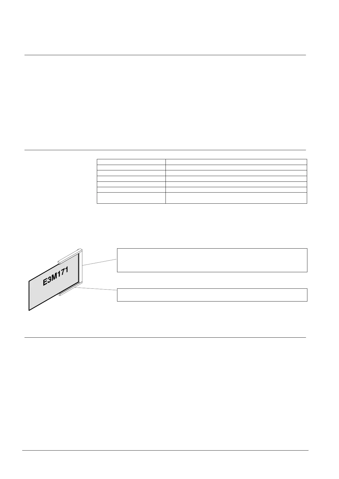
Terminal block X20 (20 terminals)
– mounted on module chassis
– for the connection of the prefabricated cable to connection level, or
– for direct connection of the periphery
Card chassis
– mounted on module chassis
21.3 Special functions
Emergency operation
– Alarm evaluation upon ”Emergency operation” via Emergency operation proc-
essor and ”Emergency operation” in the detector
– Upon emergency alarm, control console B3Q... gives a ”combined alarm” with
flashing response indicator at the detector
– Upon line short circuit and failure of the line processor there is no ”Emergency
alarm”
– Mimic display output (connectors ST10) only active with emergency alarm

 Loading...


