[ueb-einph-hochimpedanz-020926-rei, 1, en_US]
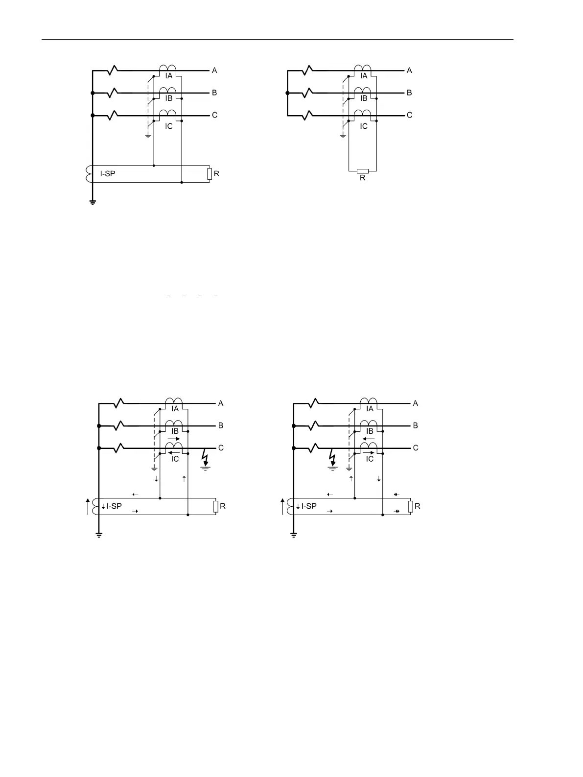
Figure 2-38 Ground fault protection according to the high-impedance principle
Function of the High-Impedance Principle
The high-impedance principle is explained on the basis of a grounded transformer winding.
No zero sequence current will flow during normal operation, i.e. the neutral point current is Ι
SP
= 0 and the
phase currents are 3 Ι
0
= Ι
A
+ Ι
B
+ Ι
C
= 0.
In case of an external ground fault (left in Figure 2-39), whose fault current is supplied via the grounded
neutral point, the same current flows through the transformer neutral point and the phases. The corre-
sponding secondary currents (all current transformers have the same transformation ratio) compensate each
other; they are connected in series. Across resistor R only a small voltage is generated. It originates from the
inner resistance of the transformers and the connecting cables of the transformers. Even if any current trans-
former experiences a partial saturation, it will become low-ohmic for the period of saturation and creates a
low-ohmic shunt to the high-ohmic resistor R. Thus, the high resistance of the resistor also has a stabilizing
effect (the so-called resistance stabilization).
[ueb-einph-hochimpedanz2-020926-rei, 1, en_US]
Figure 2-39 Principle of ground fault protection according to the high-impedance principle
When a ground fault occurs in the protected zone Figure 2-39 right), there is always a neutral point current Ι
SP
.
The grounding conditions in the rest of the network determine how strong a zero sequence current from the
system is. A secondary current which is equal to the total fault current tries to pass through the resistor R.
Since the latter is high-resistive, a high voltage emerges immediately. Therefore, the current transformers get
saturated. The RMS voltage across the resistor approximately corresponds to the knee-point voltage of the
current transformers.
Resistance R is sized such that, even with the very lowest ground fault current to be detected, it generates a
secondary voltage, which is equal to half the saturation voltage of current transformers (see also notes on
"Dimensioning" in Subsection 2.5.4 Setting Notes).
Functions
2.5 Single-Phase Overcurrent Protection
114 SIPROTEC 4, 7SJ80, Manual
E50417-G1140-C343-A8, Edition 12.2017

 Loading...


