Transformers and cable are prone to damage by overloads that last for an extended period of time. Overloads
cannot and should not be detected by fault protection. Time overcurrent protection should be set high
enough to only detect faults since these must be cleared in a short time. Short time delays, however, do
neither allow measures to discharge overloaded equipment nor do they permit to take advantage of its
(limited) overload capacity.
The 7SJ80 devices feature an overload protection function with thermal tripping characteristic adaptable to
the overload capability of the equipment being protected (overload protection with memory function).
Overload protection can be switched ON or OFF or set to Alarm Only at address 4201 FCT 49. If overload
protection is ON, tripping, trip log and fault recording is possible.
When setting Alarm Only no trip command is given, no trip log is initiated and no spontaneous fault annun-
ciation is shown on the display.
Since the 7SJ80 does not offer a connection option for an RTD box, the current temperature Θ is always equal
to zero.
The overload protection is intended to protect lines and cables against thermal overload.
NOTE
Changing the function parameters resets the thermal replica. The thermal model is frozen (kept constant),
as soon as the current exceeds the setting value 1107 I MOTOR START.
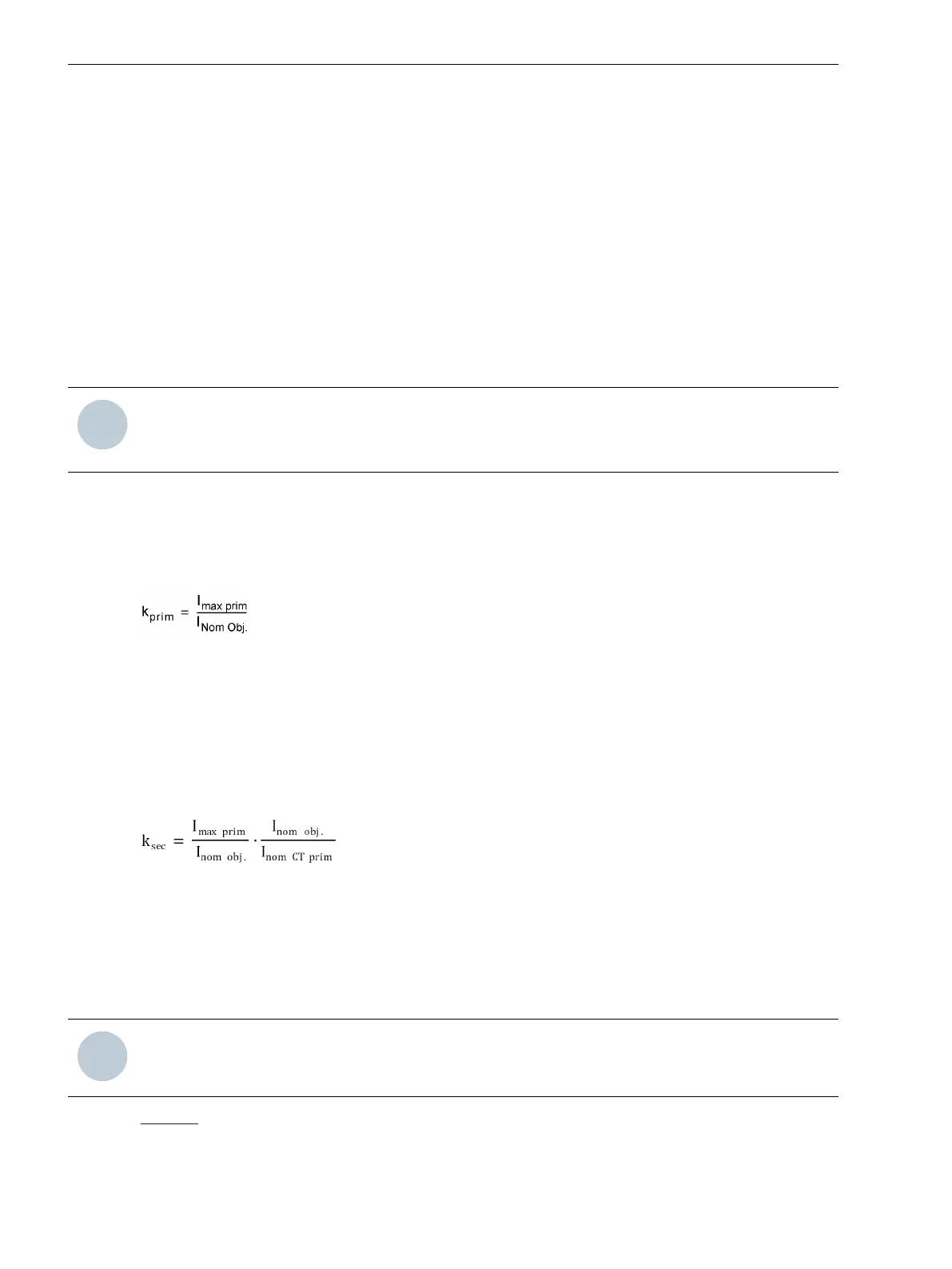
Overload Parameter k-factor
The overload protection is set in reference values. The nominal current Ι
Nom Obj.
of the protected object (motor,
transformer, cable) is used as the basic current for overload protection. By means of the thermal consistently
permissible current Ι
max
, a factor k
prim
can be calculated:
[formel-kfaktor-260602-kn, 1, en_US]
The thermally admissible continuous current for the equipment being protected is generally obtainable from
manufacturers specifications. For cables, the permissible continuous current is dependent on the cross-
section, insulating material, design, and the cable routing, among other things. It can be taken from pertinent
tables, or is specified by the cable manufacturer. If no specifications are available, select 1.1 times the nominal
current. There are usually no specifications for overhead lines but we can also assume an admissible overload
of 10% here.
For the 49 K-FACTOR to be set in the device the following applies (address 4202)
[fo_einstellwert-kfaktor-allg, 2, en_US]
with
Ι
max prim
Permissible thermal primary current of the motor
Ι
Nom Obj.
Nominal current of the protected object
Ι
NomCT prim
Nominal primary CT current
NOTE
The setting for 49 K-FACTOR (address 4202) has always to be made as a secondary value.
Example: Belted cable 10 kV, 150 mm
2
:
Permissible continuous current
Ι
max
= 322 A
Functions
2.10 Thermal Overload Protection 49
150 SIPROTEC 4, 7SJ80, Manual
E50417-G1140-C343-A8, Edition 12.2017
 Loading...


