Nominal current with k-factor 1.1
Ι
Nom Obj.
= 293 A
Current Transformer 600 A/1 A
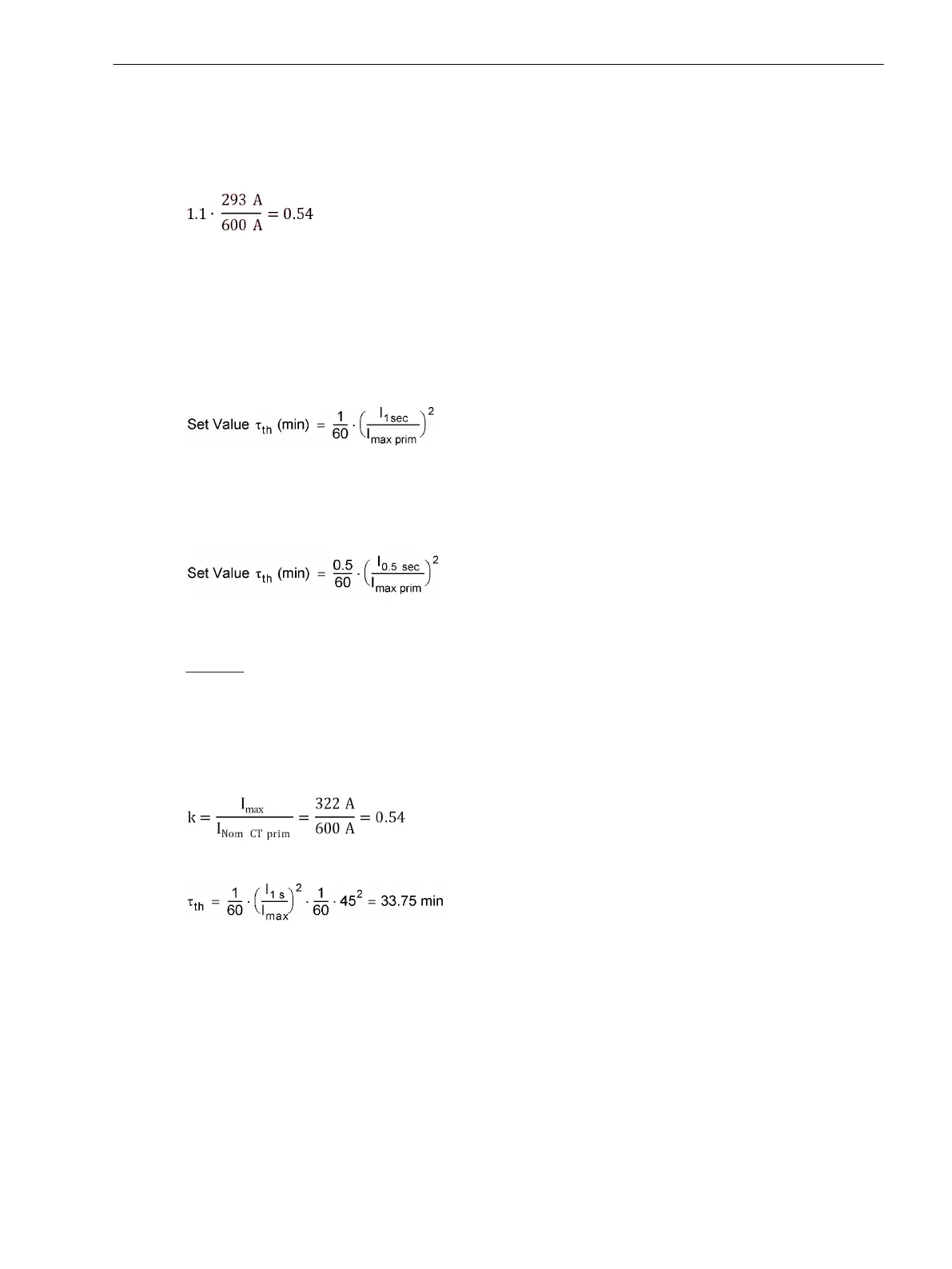
Setting value FACTOR K:
[fo_einstellwert-k-faktor_02, 1, en_US]
Time Constant τ
In lines and cables it is only the thermal time constant that is decisive for reaching the temperature rise limit.
For cable protection, the heat-gain time constant τ is determined by cable specifications and by the cable envi-
ronment. If no time-constant specification is available, it may be determined from the short-term load capa-
bility of the cable. The 1-sec current, i.e. the maximum current permissible for a one-second period of time, is
often known or available from tables. Then, the time constant may be calculated with the formula:
[einstellwert-tau-260602-kn, 1, en_US]
If the short-term load capability is given for an interval other than one second, the corresponding short-term
current is used in the above formula instead of the 1-second current, and the result is multiplied by the given
duration. For example, if the 0.5-second current rating is known:
[einstellwert-tau-05s-260602-kn, 1, en_US]
It is important to note, however, that the longer the effective duration, the less accurate the result.
Example: Cable and current transformer with the following data:
Permissible continuous current
Ι
max
= 500 A at Θ
u
= 40 °C
Maximum current for 1 s
Ι
1s
= 45 · Ι
max
= 22.5 kA
Current transformer 600 A/1 A
Thus results:
[fo_faktor-k, 1, en_US]
[formel-tau-3375-260602-kn, 1, en_US]
The settings are: 49 K-FACTOR = 0.54; TIME CONSTANT = 33.75 min
Current Limitation
To ensure that the overload protection, on occurrence of high fault currents (and with small time constants),
does not result in extremely short trip times thereby perhaps affecting time grading of the fault protection, the
thermal model is frozen (kept constant) as soon as the current exceeds the threshold value 1107 I MOTOR
START.
Functions
2.10 Thermal Overload Protection 49
SIPROTEC 4, 7SJ80, Manual 151
E50417-G1140-C343-A8, Edition 12.2017

 Loading...


