EasyManuals Logo

Siemens SIPROTEC 7SJ80 User Manual

Siemens SIPROTEC 7SJ80
562 pages
To Next Page IconTo Next Page
To Previous Page IconTo Previous Page
Page #161 background imageLoading...
Page #161 background image
[7sj80-ffm-messspg-ausfall-20120611, 2, en_US]
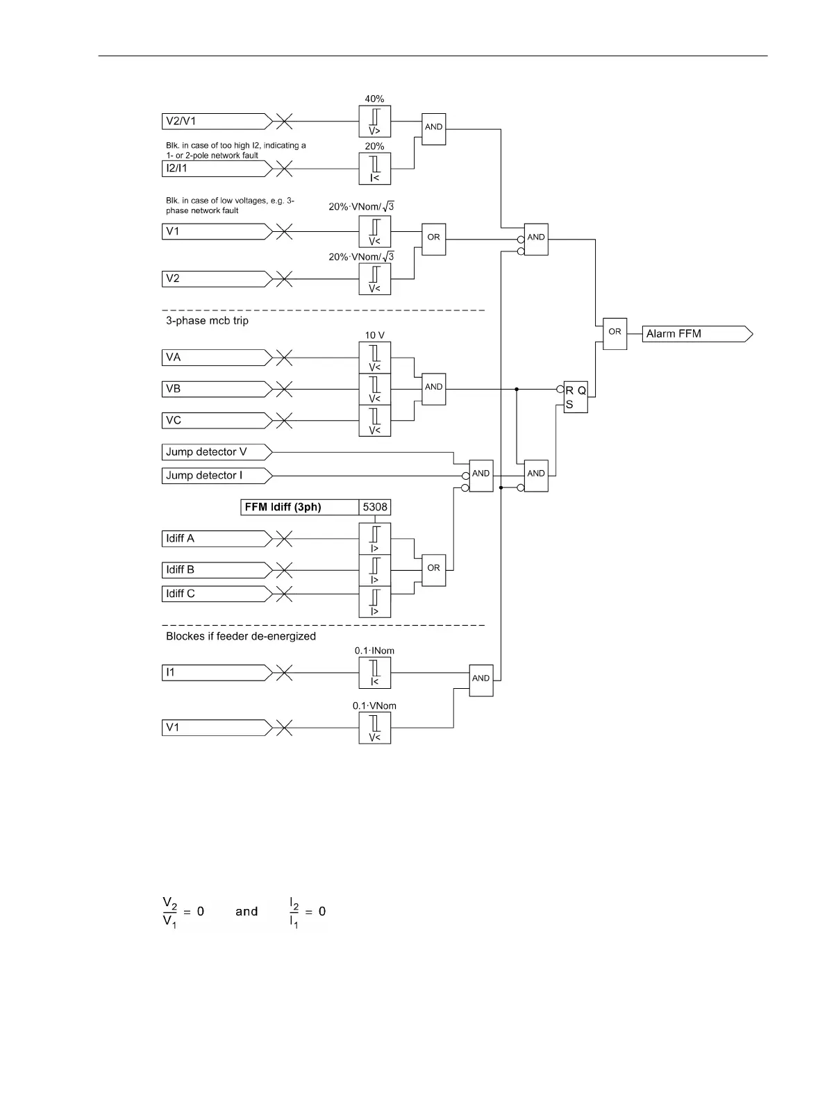
Figure 2-60
Logic diagram of the Fuse Failure Monitor for isolated and grounded systems
Single- and Two-phase Failures in Voltage Transformer Circuits
The measuring voltage failure detection is based on the fact that a significant negative sequence system is
formed in the voltage during single- or two-phase voltage failure, however without influencing the current.
This enables a clear distinction from asymmetries impressed by the power system. If the negative sequence
system is related to the current positive sequence system, the following rules apply to the Fault-free Case:
[u2-u1-fehlerfreier-fall-020828-ho, 1, en_US]
If a fault occurs in the voltage transformer secondary system, the following rules apply to the Single-phase
Failure:
Functions
2.11 Monitoring Functions
SIPROTEC 4, 7SJ80, Manual 161
E50417-G1140-C343-A8, Edition 12.2017

Table of Contents

Other manuals for Siemens SIPROTEC 7SJ80

Questions and Answers:

Question and Answer IconNeed help?

Do you have a question about the Siemens SIPROTEC 7SJ80 and is the answer not in the manual?

Siemens SIPROTEC 7SJ80 Specifications

General IconGeneral
Rated Frequency50/60 Hz
Rated Current1 A / 5 A
Operating Temperature-25°C to +55°C
Storage Temperature-40°C to +70°C
Current Transformer Inputs4
ApplicationProtection of feeders, motors, transformers, and generators
Rated Voltage100-240 V AC/DC
Communication ProtocolsIEC 61850, Modbus, DNP3, IEC 60870-5-103
DisplayGraphical LCD
MountingFlush mounting
Protection FunctionsOvercurrent, Earth fault
Communication InterfacesEthernet, RS485
HousingPlastic
WeightApprox. 1.5 kg

Related product manuals