[7sj80-fuse-failure-monitor-20061215, 1, en_US]
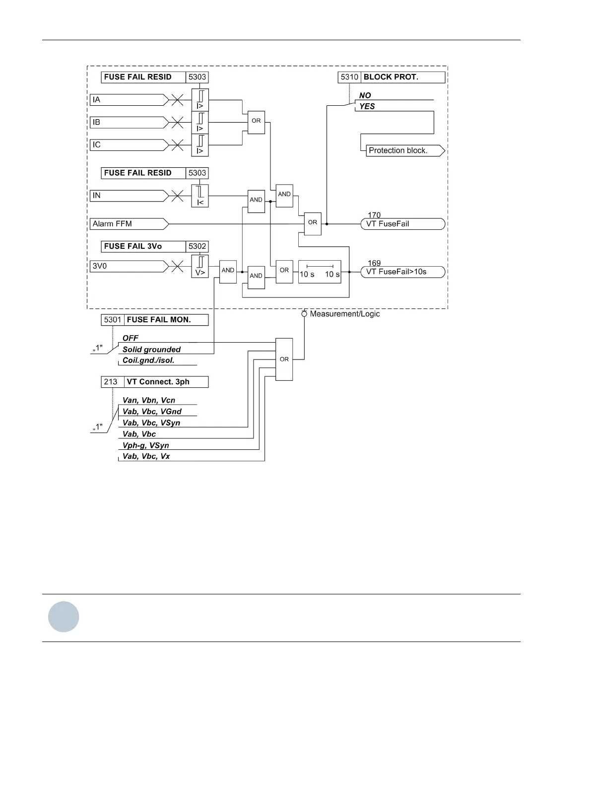
Figure 2-59
Logic diagram of the Fuse Failure Monitor for grounded networks only
Mode of Operation – Isolated System and 3-phase Fuse Failure
The FFM can also function in isolated and compensated (grounded) systems where only low ground currents
are expected. This is indicated to the device via address 5301 FUSE FAIL MON..
The logic diagram on the functioning in an isolated system and for 3-phase fuse failure is shown in
Figure 2-60. The following is a description of the principles for 1-phase, 2-phase and 3-phase faults in a secon-
dary voltage transformer system. If this part of the FFM logic picks up, the internal signal “Alarm FFM” is gener-
ated. The processing of this signal is shown in Figure 2-59.
NOTE
In isolated systems, only the following logic is used.
Functions
2.11 Monitoring Functions
160 SIPROTEC 4, 7SJ80, Manual
E50417-G1140-C343-A8, Edition 12.2017

 Loading...


