[7sj6x_ausloesekreis_2_binaerein-150502-kn, 1, en_US]
Figure 2-63 Logic diagram of the trip circuit supervision with two binary inputs
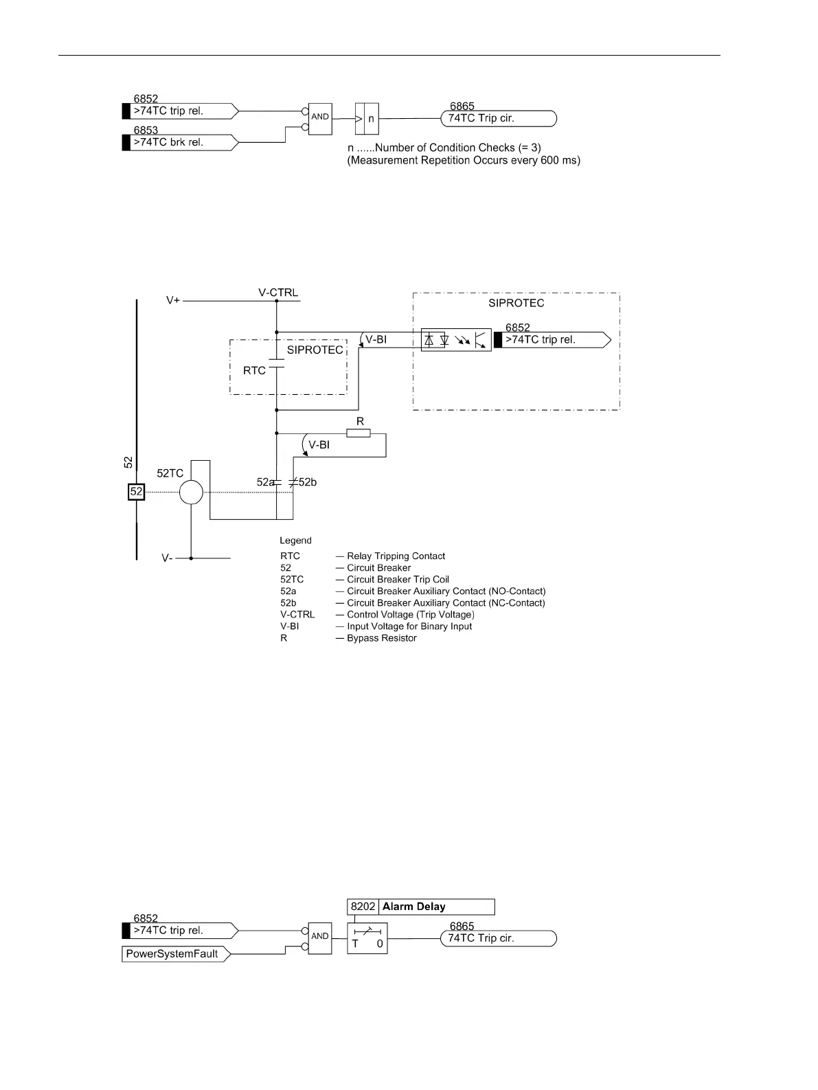
Supervision with One Binary Input
The binary input is connected according to the following figure in parallel with the associated trip contact of
the protection relay. The circuit breaker auxiliary contact is bridged with a bypass resistor R.
[prinzip-ausloesekreisueberwachung-1-binein-150502-kn, 1, en_US]
Figure 2-64
Trip circuit supervision with one binary input
During normal operation, the binary input is activated (logical condition "H") when the trip contact is open and
the trip circuit is intact, because the monitoring circuit is closed by either the 52a circuit breaker auxiliary
contact (if the circuit breaker is closed) or through the bypass resistor R by the 52b circuit breaker auxiliary
contact. Only as long as the trip contact is closed, the binary input is short circuited and thereby deactivated
(logical condition "L").
If the binary input is continuously deactivated during operation, this leads to the conclusion that there is an
interruption in the trip circuit or loss of control voltage.
As the trip circuit supervision does not operate during system faults, the closed trip contact does not lead to a
fault message. If, however, tripping contacts from other devices operate in parallel with the trip circuit, then
the fault message must be delayed (see also Figure 2-65). The delay time can be set via parameter 8202
Alarm Delay. A message is only released after expiry of this time. After clearance of the fault in the trip
circuit, the fault message is automatically reset.
[7sj6x_ausloesekreis_1_binaerein-050906-he, 1, en_US]
Figure 2-65 Logic diagram of trip circuit supervision with one binary input
Functions
2.11 Monitoring Functions
168 SIPROTEC 4, 7SJ80, Manual
E50417-G1140-C343-A8, Edition 12.2017

 Loading...


