Displacement Voltage Element V
o
The displacement voltage 64-1 VGND (address 3109) or 64-1 VGND (address 3110) is used to pick up
ground fault detection. At the same time, pickup of the voltage element is a condition for initiation of direc-
tion determination (when setting the direction characteristic to cos φ / sin φ). If the direction character-
istic is set toV0/I0 φ mea., the displacement voltage element is not relying on the current elements at all.
Depending on the configuration at address 213 VT Connect. 3ph, only the applicable limit value at address
3109 64-1 VGND or 3110 64-1 VGND is accessible.
If two phase-to-phase voltages and the displacement voltage V
0
are supplied to the device, the measured
displacement voltage is used directly for ground fault recognition. The threshold for V
0
is set at address 3109
64-1 VGND, where a more sensitive setting can be made than with a calculated displacement voltage.
Please note that when the V
0
voltage is connected, the factor (normally = 1.73; see also Section
2.1.3.2 Setting Notes) specified with parameter 206 Vph/Vdelta is used. For display of parameter 3109
64-1 VGND in primary values, the following conversion formula applies:
[formel-uenprim-uensek-120503-kn, 1, en_US]
If three phase-to-ground voltages are connected to the device, the displacement voltage 3 · V
0
is calculated
from the momentary values of phase-to-ground voltages, and address 3110 is where the threshold is to be
set. For the display of parameter 3110 in primary values, the following applies:
[formel-3u0prim-3u0sek-120503-kn, 1, en_US]
If the secondary values of (for example) parameters 3109 and 3110 are set equally, then their primary values
differ by adjustment value Vph/Vdelta.
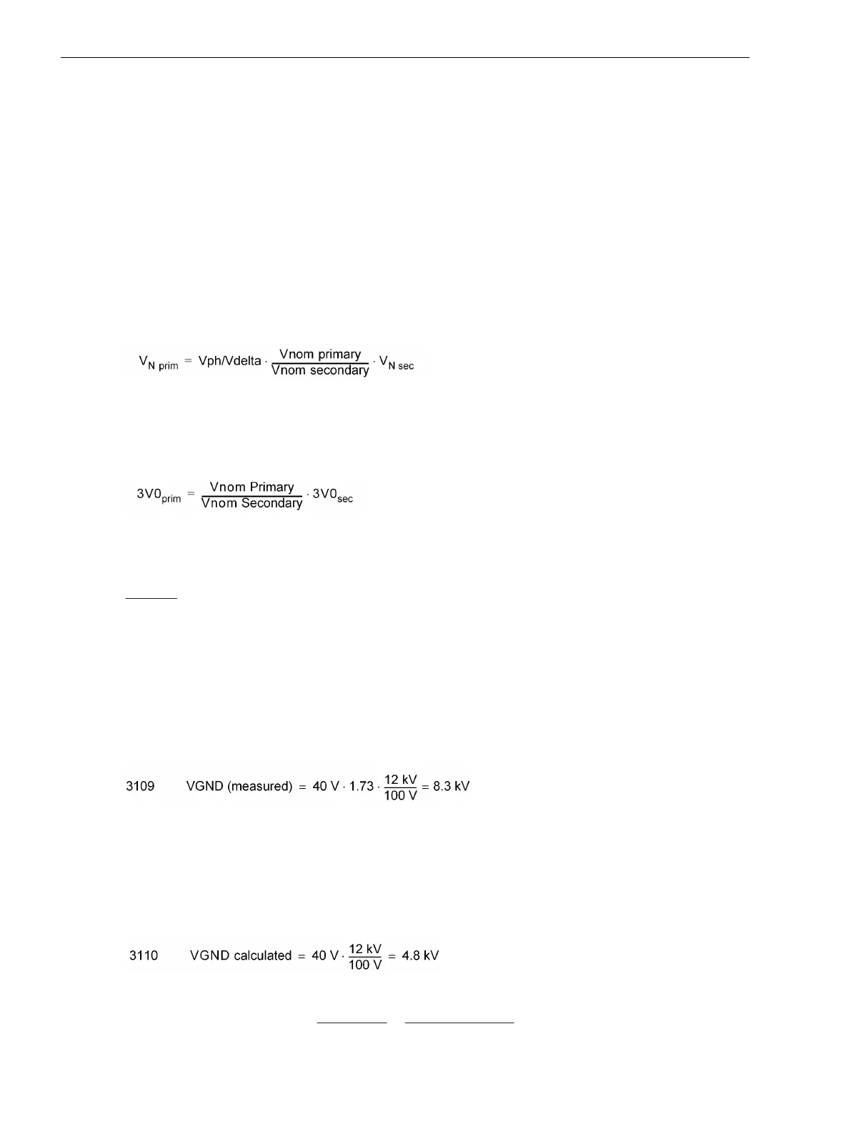
Example:
Parameter 202
Vnom PRIMARY
= 12 kV
Parameter 203
Vnom SECONDARY
= 100 V
Parameter 206
Vph/Vdelta
= 1.73
Parameter 213
VT Connect. 3ph
= Vab, Vbc,
VGnd
Parameter 3109
64-1 VGND
= 40 V
The following applies when switching to primary values:
[beispiel-uen-83kv-130503-kn, 1, en_US]
With the following configuration
Parameter 213
VT Connect. 3ph
= Van, Vbn, Vcn
Parameter 3110
64-1 VGND
= 40 V
the following applies when switching to primary values:
[beispiel-3u0-48kv-130503-kn, 1, en_US]
With regard to a ground fault in a ungrounded or resonant-grounded system, nearly the entire displacement
voltage appears at the device terminals, therefore the pickup setting is not critical, and typically lies between
Functions
2.12 Ground Fault Protection 64, 67N(s), 50N(s), 51N(s)
188 SIPROTEC 4, 7SJ80, Manual
E50417-G1140-C343-A8, Edition 12.2017

 Loading...


