The following must be observed:
•
The value pairs should be entered in increasing sequence. If desired, fewer than 20 pairs can be entered.
In most cases, about 10 pairs is sufficient to define the characteristic accurately. A value pair which will
not be used has to be made invalid by entering "∞” for the threshold! The user must ensure that the value
pairs produce a clear and constant characteristic
The current values entered should be those from Table 2-11, along with the matching times. Deviating
values Ι/Ι
p
are rounded. This, however, will not be indicated.
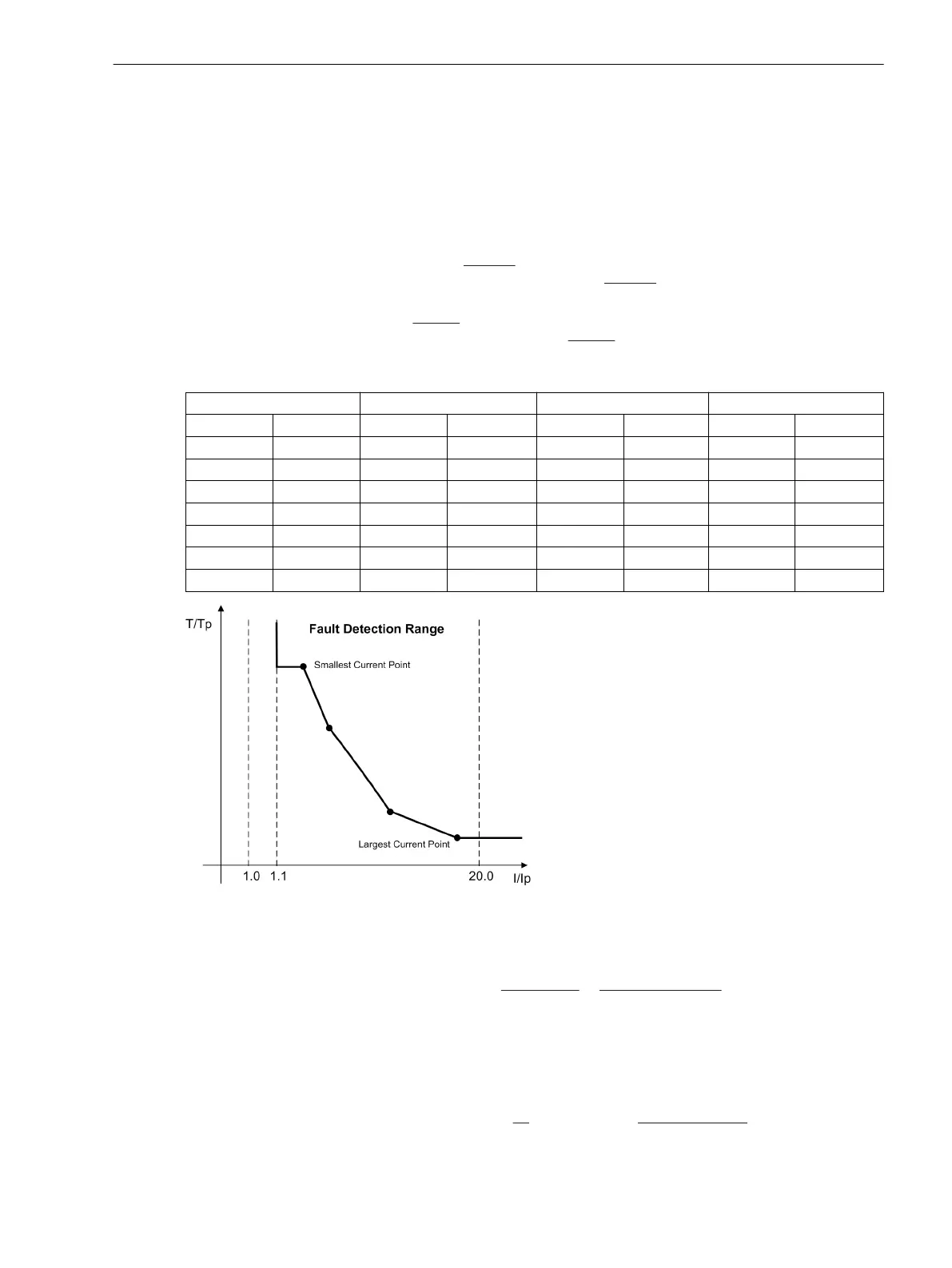
Current below the current value of the
smallest curve point will not lead to an extension of the tripping
time. The pickup curve (see Figure 2-83) continues, from the
smallest current point parallel to the current
axis.
Current flows greater than the
highest current value entered will not result in a reduced tripping time.
The pickup curve (see Figure 2-83) continues, from the
highest current point parallel to the current axis.
Table 2-11 Preferential Values of Standardized Currents for User-specific Tripping Curves
MofPU = 1 bis 1.94 MofPU = 2 bis 4.75 MofPU = 5 bis 7.75 MofPU = 8 bis 20
1.00 1.50 2.00 3.50 5.00 6.50 8.00 15.00
1.06 1.56 2.25 3.75 5.25 6.75 9.00 16.00
1.13 1.63 2.50 4.00 5.50 7.00 10.00 17.00
1.19 1.69 2.75 4.25 5.75 7.25 11.00 18.00
1.25 1.75 3.00 4.50 6.00 7.50 12.00 19.00
1.31 1.81 3.25 4.75 6.25 7.75 13.00 20.00
1.38 1.88 14.00
1.44 1.94
[verwendung-einer-anwenderspezifizierbaren-kennlinie-260602-kn, 1, en_US]
Figure 2-83 Use of a user-defined characteristic
Determination of Ground-Faulted Phase
The ground-faulted phase may be identified in an
ungrounded or resonant-grounded system, if the device is
supplied by three voltage transformers connected in a grounded-wye configuration. The phase in which the
voltage lies below setting VPH MIN at address 3106 is identified as the faulty phase as long as the other two
phase voltages simultaneously exceed the setting VPH MAX at address 3107. The setting VPH MIN must be
set less than the minimum expected operational phase-to-ground voltage. A typical setting for this address
would be 40 V. Setting VPH MAX must be greater than the maximum expected operational phase-to-ground
voltage, but less than the minimum expected operational phase-to-phase voltage. For V
Nom
= 100 V, approxi-
mately 75 V is a typical setting. These settings have no significance in a grounded system.
Functions
2.12 Ground Fault Protection 64, 67N(s), 50N(s), 51N(s)
SIPROTEC 4, 7SJ80, Manual 187
E50417-G1140-C343-A8, Edition 12.2017

 Loading...


