EasyManuals Logo

Siemens SIPROTEC 7SJ80 User Manual

Siemens SIPROTEC 7SJ80
562 pages
To Next Page IconTo Next Page
To Previous Page IconTo Previous Page
Page #254 background imageLoading...
Page #254 background image
[bsb-schaltanl-gen-eigenvers-20061205, 1, en_US]
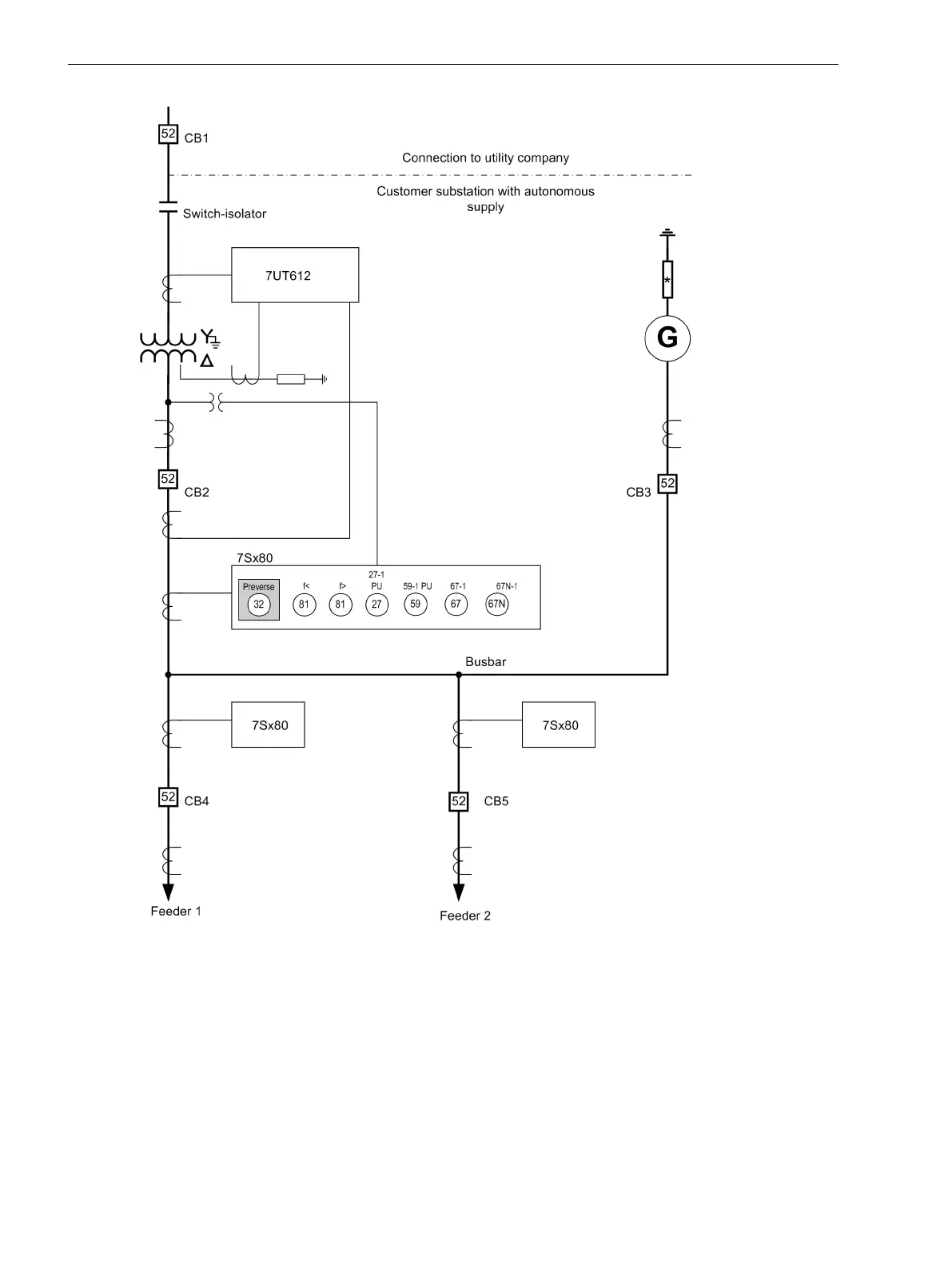
Figure 2-103
Example of a substation with autonomous generator supply
Substation Layout
The control system is on the high-voltage side linked via a 110 kV line to the power system of the power
supply company. The circuit breaker CB1 is part of the power system of the power supply company. Discon-
nection from the control system of the power supply company's power system is effected by the load-isolator.
The transformer with a transformation ratio of 10:1 transforms the voltage level to 11 kV. The transformer,
the generator and the two feeders are linked via a busbar at the low-voltage side. Circuit breakers CB2 to CB5
separate consumer and operational equipment from the busbar.
Functions
2.19 Reverse-Power Protection Application with Flexible Protection Function
254 SIPROTEC 4, 7SJ80, Manual
E50417-G1140-C343-A8, Edition 12.2017

Table of Contents

Other manuals for Siemens SIPROTEC 7SJ80

Questions and Answers:

Question and Answer IconNeed help?

Do you have a question about the Siemens SIPROTEC 7SJ80 and is the answer not in the manual?

Siemens SIPROTEC 7SJ80 Specifications

General IconGeneral
Rated Frequency50/60 Hz
Rated Current1 A / 5 A
Operating Temperature-25°C to +55°C
Storage Temperature-40°C to +70°C
Current Transformer Inputs4
ApplicationProtection of feeders, motors, transformers, and generators
Rated Voltage100-240 V AC/DC
Communication ProtocolsIEC 61850, Modbus, DNP3, IEC 60870-5-103
DisplayGraphical LCD
MountingFlush mounting
Protection FunctionsOvercurrent, Earth fault
Communication InterfacesEthernet, RS485
HousingPlastic
WeightApprox. 1.5 kg

Related product manuals