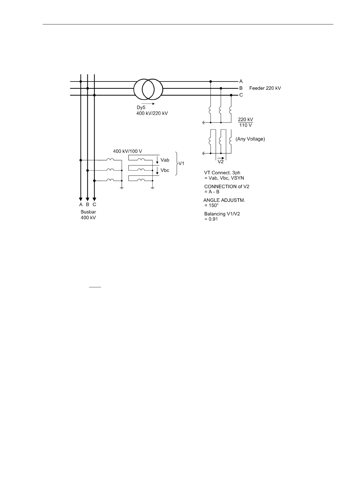
Address 6122 ANGLE ADJUSTM. = 150°.
The reference voltage transformers supply 100 V secondary for primary operation at nominal value while the
feeder transformer supplies 110 V secondary. Therefore, this difference must be balanced:
Address 6121 Balancing V1/V2 = 100 V/110 V = 0.91.
[ss-spg-ueber-trafo-gemess-061115, 1, en_US]
Figure 2-117 Busbar voltage measured across the transformer
Voltage Connections
The 7SJ80 provides two voltage inputs for connecting the voltage V
1
and one voltage input for connecting the
voltage V
2
(see the following examples).
If two phase-to-phase voltages are open delta-connected to side V
1
as reference voltage, a phase-to-phase
voltage
must be connected and configured for the additional voltage V
2
to be synchronized.
To correctly compare the phase-to-phase reference voltage V
1
with the additional voltage V
2
, the device needs
to know the connection type of voltage V
2
. That is the task of parameter CONNECTIONof V2 (parameter
6123).
For the device to perform the internal conversion to primary values, the primary rated transformer voltage of
the measured quantity V
2
must be entered via parameter 6125 VT Vn2, primary, primary if a transformer
is located between the system parts to be synchronized.
Functions
2.20 Synchrocheck
SIPROTEC 4, 7SJ80, Manual 269
E50417-G1140-C343-A8, Edition 12.2017

 Loading...


