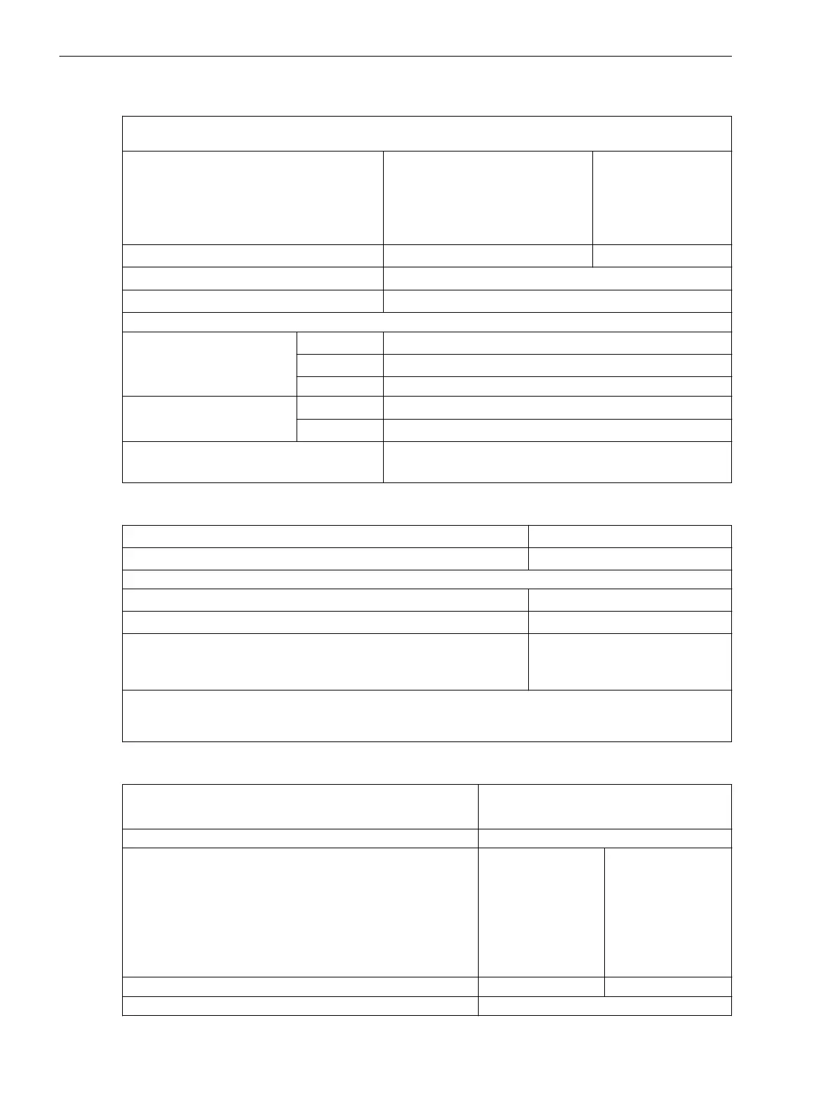
Ground Fault Pickup for All Types of Ground Faults (Inverse Time Characteristic)
User-defined characteristic (defined by a maximum of 20 value pairs of current and time delay in direction
measurement method "cos phi and sin phi")
Pickup current 51Ns
for sensitive 1 A transformer
for sensitive 5 A transformer
for normal 1 A transformer
for normal 5 A transformer
0.001 A to 1.400 A
0.005 A to 7.000 A
0.05 A to 4.00 A
0.25 A to 20.00 A
Increments 0.001 A
Increments 0.005 A
Increments 0.01 A
Increments 0.05 A
Time multiplier T
51Ns
0.10 s to 4.00 s or ∞ (disabled) Increments 0.01 s
Pickup threshold
approx. 1.10 · Ι
51Ns
Dropout ratio
approx. 1.05 · Ι
51Ns
for Ι
51Ns
> 50 mA
Measurement tolerance
sensitive
for Ι
Nom
= 1 A
3 % of setting value or 1 mA
for Ι
Nom
= 5 A
3 % of setting value or 5 mA
for setting values < 10 mA ca. 20 %
non-sensitive
for Ι
Nom
= 1 A
3 % of setting value or 15 mA
for Ι
Nom
= 5 A
3 % of setting value or 75 mA
Operating time tolerance in linear range 7 % of reference (calculated) value for
2 ≤ Ι/Ι
51Ns
≤ 20 + 2 % current tolerance, or 70 ms
Influencing Variables
Auxiliary DC voltage in range 0.8 ≤ V
Aux
/V
AuxNom
≤ 1.15 1 %
Temperature in range –5 °C (23 °F) ≤ Θ
amb
≤ 55 °C (131 °F) 0.5 %/10 K
Frequency in the range of 25 Hz to 70 Hz
Frequency in the range of 0.95 ≤ f/f
Nom
≤ 1.05 (f
Nom
= 50 Hz or 60 Hz) 1 %
Frequency outside range 0.95 ≤ f/f
Nom
≤ 1.05 Increased tolerances
Harmonics
- up to 10 % 3rd harmonic
- up to 10 % 5th harmonic
1 %
1 %
Note: When using the sensitive transformer, the linear range of the measuring input for sensitive ground
fault detection is from 0.001 A to 1.6 A or 0.005 A to 8.0 A, depending on parameter 205 CT SECONDARY.
The function is however still preserved for larger currents.
Direction Determination for all Types of Ground Fault with cos ϕ / sin ϕ Measurement
Direction measurement
- Ι
N
and V
N
measured
- 3Ι
0
and 3V
0
calculated
Measuring principle Active/reactive power measurement
Measuring release RELEASE DIRECT.
(current component perpendicular (90º) to directional limit
line)
for sensitive 1 A transformer
for sensitive 5 A transformer
for normal 1 A transformer
for normal 5-A transformer
0.001 A to 1.600 A
0.005 A to 8.000 A
0.05 A to 35.00 A
0.25 A to 175.00 A
Increments 0.001 A
Increments 0.005 A
Increments 0.01 A
Increments 0.05 A
Dropout ratio approx. 0.80
Measurement method cos φ and sin φ
Technical Data
4.14 Ground Fault Detection (Sensitive/Insensitive)
396 SIPROTEC 4, 7SJ80, Manual
E50417-G1140-C343-A8, Edition 12.2017

 Loading...


