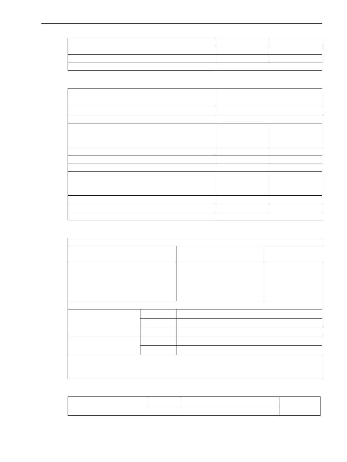
Directional limit line PHI CORRECTION -45.0° to +45.0° Increments 0.1°
Dropout delay RESET DELAY 1 s to 60 s Increments 1 s
Limitation of the directional areas using α1 and α2 1° to 15° Increments 1°
Angle tolerance 3°
Direction Determination for all Types of Ground Fault with V0 ϕ / I0 ϕ Measurement
Direction measurement
- Ι
N
and V
N
measured
- 3Ι
0
and 3V
0
calculated
Measuring principle
V0 / Ι0 phase angle measurement
50Ns-1 element
Minimum voltage 50Ns-1 Vmin
V0 measured
3V0 calculated
0.4 V to 50 V
10 V to 90 V
Increments 0.1 V
Increments 1 V
Phase angle 50Ns-1 Phi - 180° tos 180° Increments 1°
Delta phase angle 50Ns-1 DeltaPhi 0° bis 180° Increments 1°
50Ns-2 element
Minimum voltage 50Ns-2 Vmin
V0 measured
3V0 calculated
0.4 V to 50 V
10 V to 90 V
Increments 0.1 V
Increments 1 V
Phase angle 50Ns-2 Phi - 180° to 180° Increments 1°
Delta phase angle 50Ns-2 DeltaPhi 0° to 180° Increments 1°
Angle tolerance 3°
Angle tolerance
Angle correction for cable converter in two operating points F1/I1 and F2/I2:
Angle correction F1, F2
(for resonant-grounded system)
0.0° to 5.0° Increments 0.1°
Current values Ι1, Ι for angle correction
for sensitive 1 A transformer
for sensitive 5 A transformer
for normal 1 A transformer
for normal 5 A transformer
0.001 A to 1.600 A
0.005 A to 8.000 A
0.05 A to 36.00 A
0.25 A to 175.00 A
Increments 0.001 A
Increments 0.005 A
Increments 0.01 A
Increments 0.05 A
Measurement tolerance
sensitive
for Ι
Nom
= 1 A
3 % of setting value or 1 mA
for Ι
Nom
= 5 A
3 % of setting value or 5 mA
for setting values < 10 mA ca. 20 %
non-sensitive
for Ι
Nom
= 1 A
3 % of setting value or 15 mA
for Ι
Nom
= 5 A
3 % of setting value or 75 mA
Note: Due to the high sensitivity, the linear range of the measuring input Ι
N
with integrated sensitive input
transformer is from 0.001 · Ι
Nom
to 1.6 · Ι
Nom
. For currents greater than 1.6 · Ι
Nom
, correct direction determina-
tion can no longer be guaranteed.
EPTR Setting Ranges / Increments
Pickup current
for Ι
N
= 1 A
0.001 A to 2.400 A Incre-
ments0.001 A
for Ι
N
= 5 A
0.005 A to 7.000 A
Technical Data
4.14 Ground Fault Detection (Sensitive/Insensitive)
SIPROTEC 4, 7SJ80, Manual 397
E50417-G1140-C343-A8, Edition 12.2017

 Loading...


