occurrence of a fault in the phase element, address 1213 MANUAL CLOSE has to be set accordingly. Corre-
spondingly, address 1313 MANUAL CLOSE is considered for the ground path address. Thus, the user deter-
mines for both elements, the phase and the ground element, what pickup value is active with what delay
when the circuit breaker is closed manually.
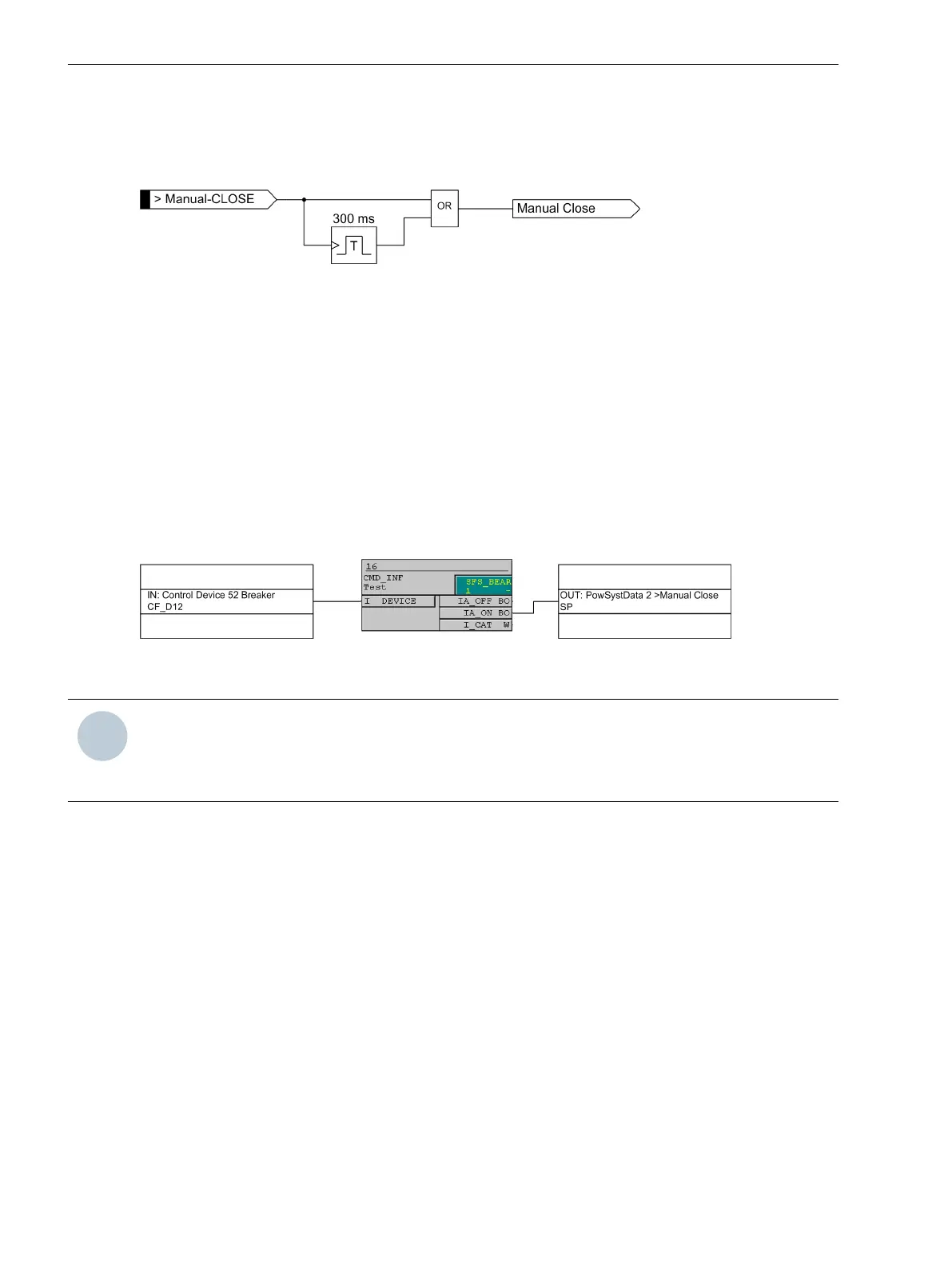
[lo_7sj6-hand-ein, 1, en_US]
Figure 2-17 Manual close feature
External Control Command
If the manual close signal is not sent from 7SJ80 device, i.e. neither via the built-in operator interface nor via a
serial interface, but directly from a control acknowledgment switch, this signal must be passed to a 7SJ80
binary input, and configured accordingly (
>Manual Close
), so that the element selected for MANUAL
CLOSE can become effective. The alternative Inactive means that all elements operate as per configuration
even with manual close and do not get special treatment.
Internal Control Function
If the manual close signal is sent via the internal control function of the device, an internal connection of
information has to be established via CFC (interlocking task level) using the CMD_Information block (see
Figure 2-18).
[handein-260602-kn, 1, en_US]
Figure 2-18 Example for the generation of a manual close signal using the internal control function
NOTE
For an interaction between the automatic reclosing function (79 AR) and the control function, an extended
CFC logic is necessary. See margin heading “Close command: Directly or via Control” in the Setting Notes of
the automatic reclosing function (Section 2.15.6 Setting Notes).
Interaction with the Automatic Reclosing Function (phases)
If reclosing follows, high-speed and simultaneous protection against faults with 50-2 or 50-3 is usually
desired. If the fault still exists after the first reclosing, the 50-1 or the 51 element will be initiated with graded
tripping times, that is, element 50-2 or 50-3 will be blocked. You can use the parameters 1214 50-2 active
or 1216 50-3 active active for this purpose to define whether or not the 50-2 or the 50-3 element is
impacted by a release signal of the internal or an external automatic reclosing system. The setting with 79
active means that the 50-2 or the 50-3 element will only be released if automatic reclosing is not blocked. If
this is not desired, the setting Always is selected so that the 50-2 or the 50-3 element is always active.
The integrated automatic reclosing function of 7SJ80 also provides the option to individually determine for
each overcurrent element whether tripping or blocking is to be carried out instantaneously or unaffected by
the AR with the set time delay (see Section 2.15 Automatic Reclosing System 79).
Interaction with the Automatic Reclosing Function (ground)
When reclosing occurs, it is desirable to have high-speed protection against faults with 50N-2 or 50N-3. If the
fault still exists after the first reclosing, the 50N-1 or the 51N element will be initiated with coordinated trip-
ping times, that is, element 50N-2 or 50N-3 will be blocked. At address 1314 50N-2 active or 1316 50N-3
active active it can be specified whether the 50N-2 or the 50N-3 element should be influenced by the
Functions
2.2 Overcurrent Protection 50, 51, 50N, 51N
76 SIPROTEC 4, 7SJ80, Manual
E50417-G1140-C343-A8, Edition 12.2017

 Loading...


