Functional Parameter Table
V800 Series High Performance Closed-Loop Vector Inverter User Manual
Spindle positioning selection 1
Spindle positioning selection 2
Spindle positioning selection 3
Servo command pulse value clear
0.1Hz~100.00KHz pulse input(DI9/Fin
Effective)
Pulse input(DI9/Fin Effective)
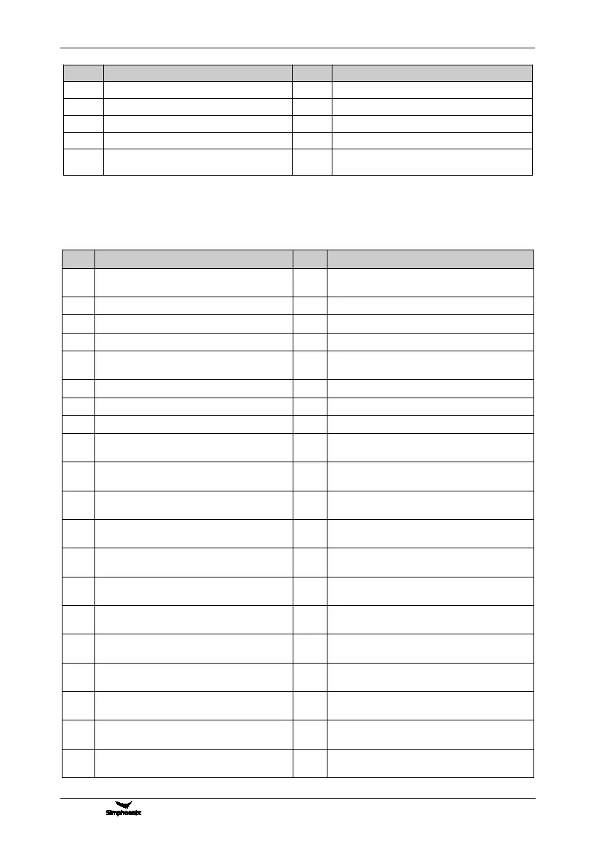
Table 2: Comparison Table of Multifunctional Output Terminal (DO/EDO/SDO)
Variables
Inverter running ready (normal voltage, no
emergency stop input)
Equipment normal (fault-free running)
Running command input (irrelevant with start
or running signal)
Inverter under voltage stop
Terminal control effective
In the process of acceleration running
In the process of deceleration running
Braking power generation running status
Determined by standard MODBUS Fieldbus
Determined by Extended communication
module
Completion of current stage of multi-stage
running (0.5s pulse )
Multi-stage running completed (0.5s pulse )
Multi-stage running completed (continuous level
output)
Multi-stage running cycle completed (0.5s
pulse )
Swing frequency upper and lower limit
Encoder direction positive (A pulse
surpassing B pulse )
Encoder direction negative (A behind B)
Monitor 1 input variable below the lower limit
(Void when above the upper limit)
Monitor 1 input variable above the upper
limit(void when below the lower limit)
Monitor 1 input variable between the upper
limit and the lower limit
Monitor 2 variable below the lower limit (void
when above the upper limit)
Monitor 2 input variable above the upper
limit(void when below the lower limit)
Monitor 2 input variable between the upper limit
and the lower limit
Monitor 3 input variable below the lower
limit(void when above the upper limit)
Monitor 3 input variable above the upper limit
(void when below the lower limit)
Monitor 3 input variable between the upper
limit and the lower limit
Position reached (Servo or spindle control)
Analog input AI1 wire breakage detection
effective
Analog input AI2 wire breakage detection
effective
Analog input AI3 wire breakage detection
effective