561
Serial Port Settings (Serial Port Assign Menu)
Chapter 22 DCU Setup (DCU)
The input device name appears in the device name list.
To return the device name for the selected ID to the
default name
Press [Clear] in the <Name> group.
7
Using any of the following methods, specify the
command to which the response speed setting applies.
• Press directly on the delay list in the status area.
• Press the arrow keys to scroll the reverse video
cursor.
• Turn the knob.
8
Turn the knob to set the response speed (in field units) of
the device.
9
Press [Delay Set].
10
Repeat steps 4 to 9 as required to make the settings for
other commands.
Making detailed settings for a VTR
1
In the <DCU Select> group of the DCU >Serial Port
Assign menu, select the target for the setting (DCU1 or
DCU2).
2
Using any of the following methods, select the serial
port connected to the VTR for which you want to make
the settings.
• Press directly on the list in the status area.
• Press the arrow keys to scroll the reverse video
cursor.
• Turn the knob.
a) The range of setting values depends on the DCU port setting. (When
the MKS-2700 is connected, select 2 for the slot and a value in the
range 1 to 6 for the port.)
3
Press [Port Setting].
The DCU >Serial Port Assign >VTR Setting menu
appears.
At the top of the status area, the relevant serial port,
slot number, protocol, serial port name, SCU number,
and timecode source appear. In the lower part of the
status area, the VTR constants appear.
4
In the <TC Source> group, select the timecode source
(reference signal for determining the tape position)
from the following.
LTC (Longitudinal Time Code): Use LTC. When
interpolation data is returned from a VTR, use that
interpolation data.
LTC: VITC (Vertical Interval Time Code):
Normally use LTC, but when the tape is moving at
speeds at which LTC cannot be read, use VITC.
When interpolation data is returned from a VTR,
use that interpolation data.
VITC: Use VITC.
CTL (Control): CTL pulses or timer counter pulses
are used. Use this only for a tape on which no
timecode is recorded.
The displayed tape position is based on the reference
signal specified here.
5
Using any of the following methods, specify the VTR
constants.
• Press directly on the list in the status area.
• Press the arrow keys to scroll the reverse video
cursor.
• Turn the knob.
6
Press [Set].
A numeric keypad window for hexadecimal input
appears.
7
Set the VTR constants using values in the range 00 to
FF.
Knob Parameter Adjustment Setting values
2No Command
number
selection
1 to 18
Knob Parameter Adjustment Setting values
3 Delay Response speed
setting
0 to 60
Knob Parameter Adjustment Setting values
1 Port No Serial port 1 and
upwards
a)
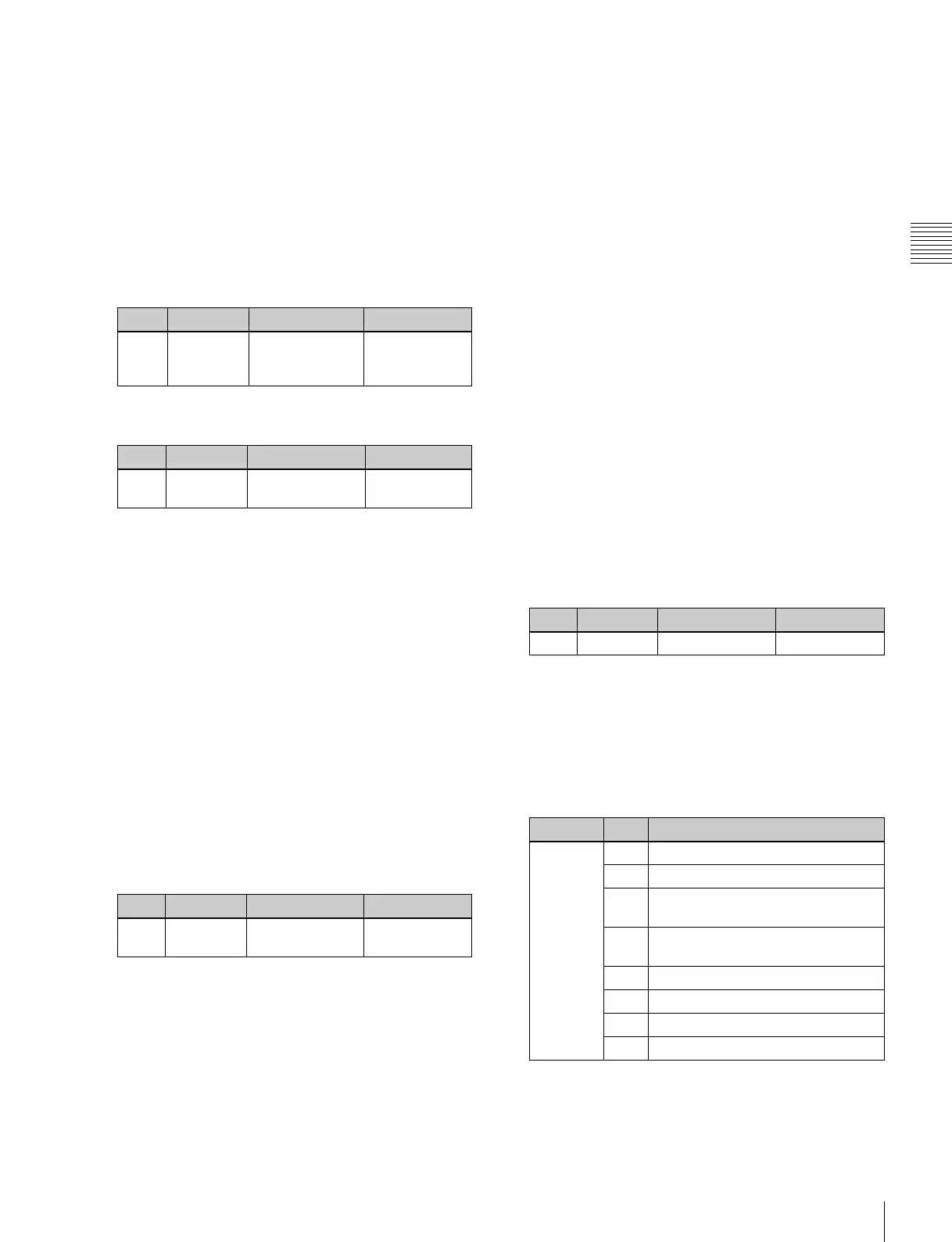
Knob Parameter Adjustment Setting values
1 Item Item selection 1 to 16
Block Byte Setting item
BLOCK 1 1 HI-BYTE (DEVICE TYPE)
2 LO-BYTE (DEVICE TYPE)
3 HI-BYTE (FRAME) (PREROLL
TIME)
4 LO-BYTE (FRAME) (PREROLL
TIME)
5 EDIT DELAY (FRAME)
6 EE DELAY (FRAME)
7 OVER RUN (FRAME)
8 TRAJECTORY
 Loading...


