146
D. If your printer’s part placement setting is On (see “Part Placement” on page 81), the Part
Placement page will display. The calibration part location is fixed and can not be moved.
Press the Print button (pressing the Clear button will clear the display, removing all "ghost
box" items).
E. The calibration part will begin the print process and display the current status on the User
Interface. "HEATING" or “COOLING” is followed by "PREPARING" and then “PRINTING“.
• The Heating/Cooling status displays the current temperature as well as the target set point.
• The Preparing status will display as the system purges material and detects the tray level.
• The Printing status displays the number of build layers complete or the amount of time remaining.
Tap the screen to toggle between layers or time.
F. Once the calibration part is complete "DONE" will be displayed on the User Interface.
Remove the substrate from the platen. You will analyze the part on the substrate to
determine correction values
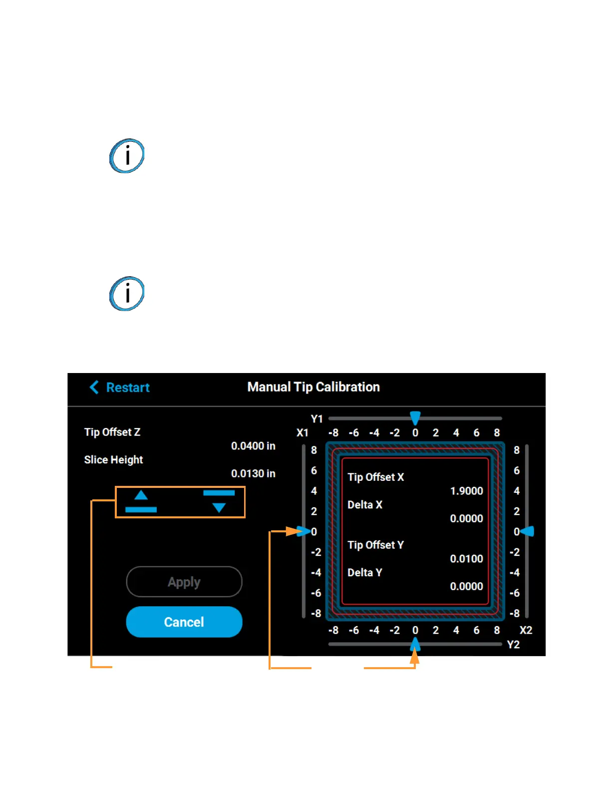
G. Press the Next button in the upper-right corner of the page; the Manual Tip Calibration page
will be displayed.
Figure 6-9: Manual Tip Calibration Page
Note: The amount of time that the printer remains in the Heating/Cooling stage
may vary depending on the current oven chamber temperature.
Note: After removing the substrate containing the calibration part and closing
the oven door, a message is displayed stating “Is the tray ready for another
job?”. Press No to return to the Manual Tip Calibration screen.
Sliding scale
icons
Up and down
adjustment buttons