147
2. Determine the XY Offset Adjustment needed for your printer.
A. Using a magnifier (included in the Welcome Kit), view the relationship between the support
calibration toolpath and the alignment indicators to determine the X and Y axis calibration.
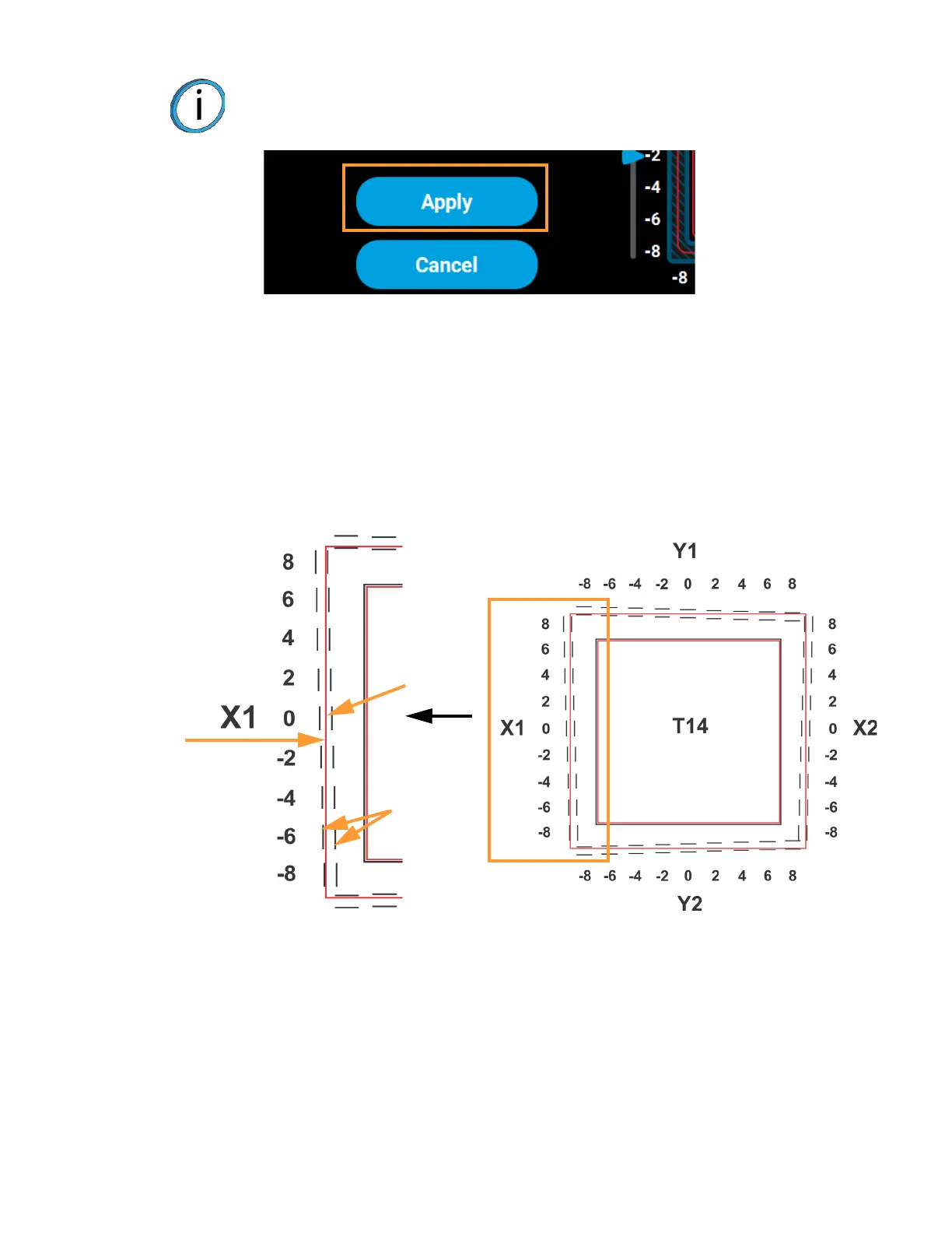
B. Determine where on each side (X1, X2, Y1, and Y2) the support toolpath is most centered
between the X-Y alignment indicators (see Figure 6-10 or Figure 6-11). The numbers on the
calibration part represent thousandths of an inch (e.g., 4 = 0.004 in.).
Figure 6-10: Calibration Part
Note: The Apply button will become active when you modify an offset value by
dragging the sliding scale icons or pressing the up and down adjustment
buttons.
Calibration Part
Alignment
indicators
Support
toolpath
Magnified single side of a calibration part with a reading of 0.
Most
centered
at 0