148
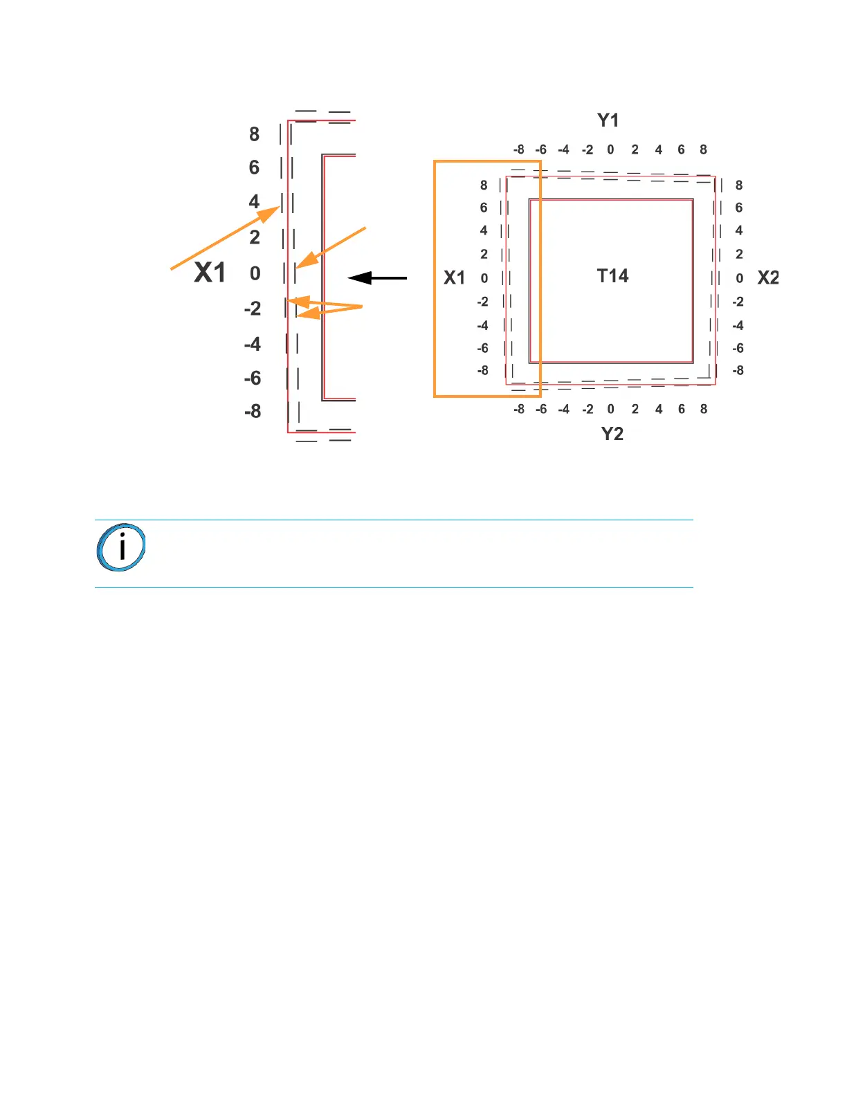
Figure 6-11: Calibration Part
C. Within the Manual Tip Calibration page, slide all four of the scale icons on the screen to
match where the support toolpath is most centered between the alignment indicators. The
Delta X and Delta Y fields will change to reflect adjustments made.
• If the Delta X and the Delta Y values are both within the range of -0.002 to +0.002 in., the printer
is calibrated and an adjustment is not required. The following figure shows an XY offset within
tolerance, requiring no adjustments. Proceed to step 3.
Note: One offset value must be selected for each side (X1, X2, Y1 and Y2).
Calibration Part
Support
toolpath,
most
centered
at 4
Not
centered
at 0
Support toolpath is most centered between the alignment
indicators at the 4, indicating an adjustment of X1 = 0.004
Alignment
indicators