151
3. Determine the Z Offset Adjustment.
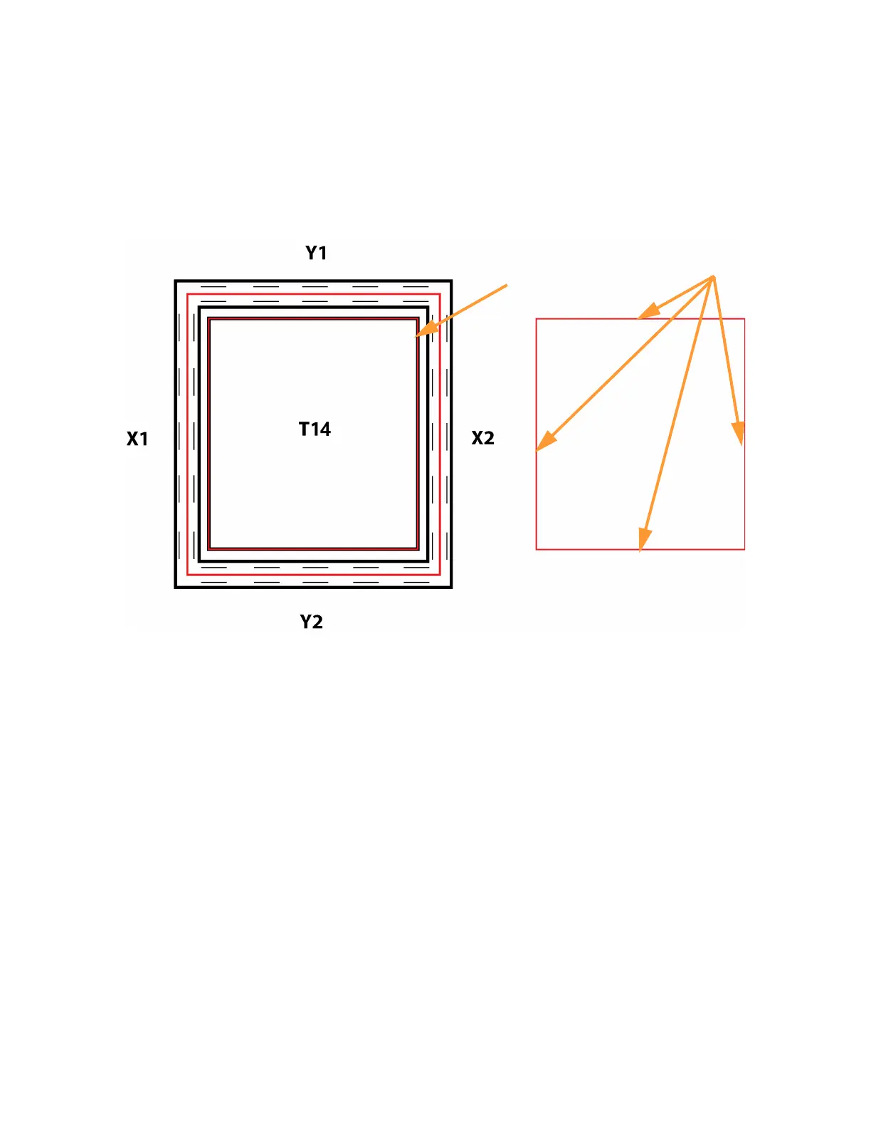
A. Peel the support layer from the inner square of the calibration part.
B. Measure the thickness of the support layer on each side of the square with a caliper or
micrometer. Measure in the center of each side; measuring near the corners will result in
inaccurate values.
C. Take the average value of the four measurements. This is the number you will enter for the Z
offset adjustment.
Figure 6-15: Remove and Measure Support Layer
D. If the value measured in step C is within ±0.0005 in. (0.01 mm) of the model tip’s slice height
of 0.010 in. (0.254 mm), the printer is calibrated for the Z axis and an adjustment is not
required. Proceed to step 4.
E. If the value measured in step C is not within ±0.0005 in. (0.01 mm) of the model tip’s slice
height you will need to enter a Z offset adjustment using the Up and Down buttons within the
Manual Tip Calibration page. Each button press equates to one ten thousandths of an inch.
Peel support
layer here
Measure support layer
here (on all 4 sides)