1-28 280C-009-002 REV B www.stryker.com
Return To Table of Contents
English
HEAD END SIDERAIL ASSEMBLY REPLACEMENT
Tools Required:
• 1/2” Socket
• 3/8” Drive Ratchet
• 3/16” Allen Wrench
• Cutting Pliers
Procedure:
1. Raise the bed to the highest position and apply the brakes.
2. If applicable, remove the plastic litter cover (if equipped). Raise the fowler to the highest position and raise the
siderail to be repaired.
3. Unplug the power cord from the wall receptacle.
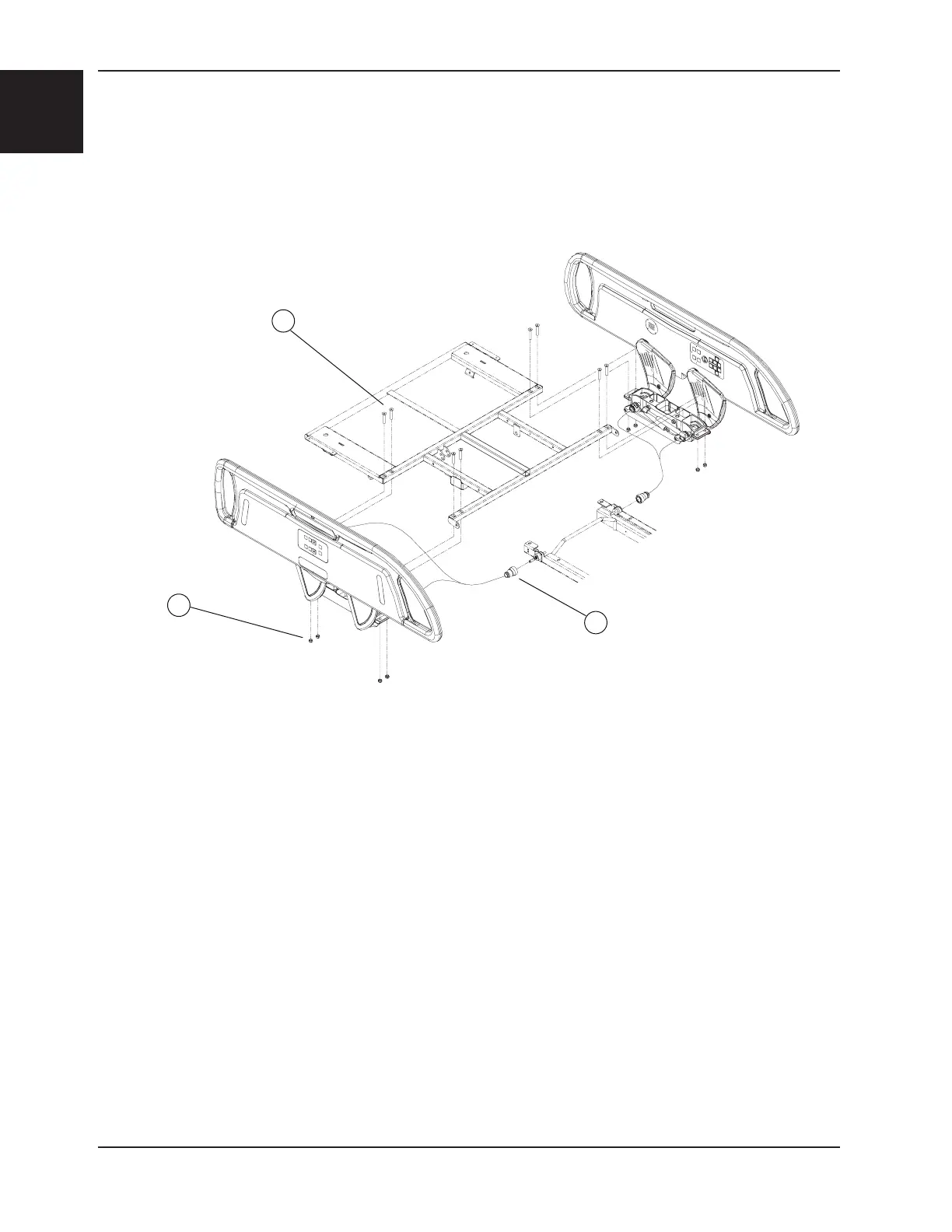
4. Loosen the lock ring (A) and unplug the siderail cable.
5. Using cutting pliers, remove the cable ties holding the siderail cable to the frame.
6. Using a 3/16” Allen wrench and a 1/2” socket, remove the four locknuts/bolts (B) holding the siderail assembly to
the head section and remove the assembly. Support the assembly when removing the last bolts.
7. Reverse the above steps to install the new siderail assembly.
8. Test the siderail movement and all controls of both control panels, including the nurse call (optional) and the
communications package (optional), for proper operation before returning the bed to service.
B
B
Figure 1
Service Information

 Loading...