1-48 280C-009-002 REV B www.stryker.com
Return To Table of Contents
English
Tools Required:
• #2 Phillips Screwdriver
Procedure:
1. Raise the bed to the highest position and apply the
brakes.
2. Unplug the bed power cord from the wall outlet.
3. Remove the power cord from the power connector and
disengage it from the wire clip.
4. Properly ground yourself (see “Grounding Diagram”
page 1-13).
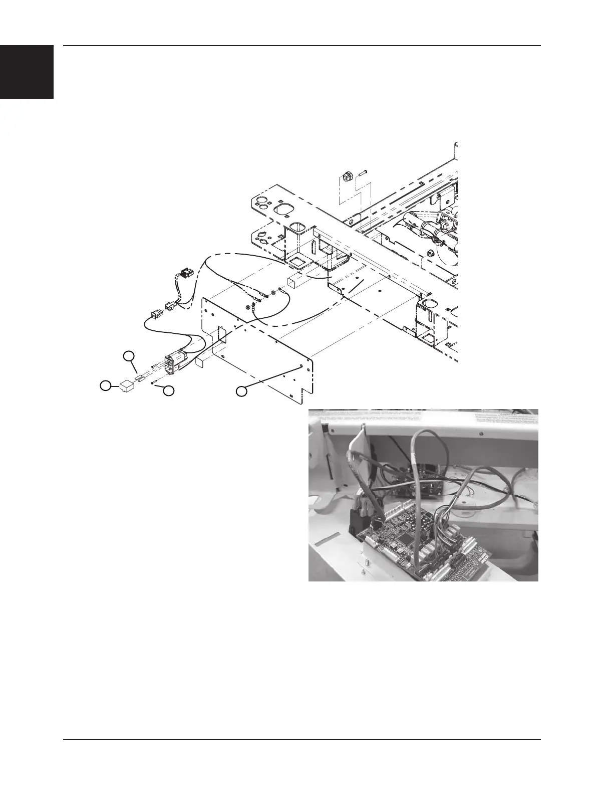
5. Using a #2 Phillips screwdriver, remove the six screws
(A) holding the cover to the litter. Keep the cable clips.
6. Once the screws removed, pivot the cover and lay it flat
on the bottom of the litter (see opposite illustration).
7. Remove all cables connected to the control board. Note
their location so they will be connected properly to the new board. Refer to drawing OL280120, page 1-88, or
OL280121, page 1-94, for the connecting position of the cables on the power connector.
8. Turn the cover to a vertical position and. Using a #2 Phillips screwdriver, remove the four screws (B) holding the
control board (C) to the head casing cover and remove the board.
9. Reverse the above steps to install the new control board. Before installing the new board, ensure the dip switch
settings on the new board match the ones on the old board.
10. Test the nurse call for proper operation before returning the bed to service.
HEADWALL CONTROL BOARD REPLACEMENT (OPTIONAL)
Service Information
E
E'
Figure 12
A
B
C
D
 Loading...