www.stryker.com 280C-009-002 REV B 1- 51
Return To Table of Contents
English
Tools Required:
• #2 Phillips Screwdriver
• 3/8” Combination Wrench
• Needle Nose Pliers
Procedure:
1. Raise the bed to the highest position and apply the brakes.
2. If applicable, remove the plastic litter cover (if equipped) and raise the fowler to the highest position.
3. Unplug the power cord from the wall receptacle.
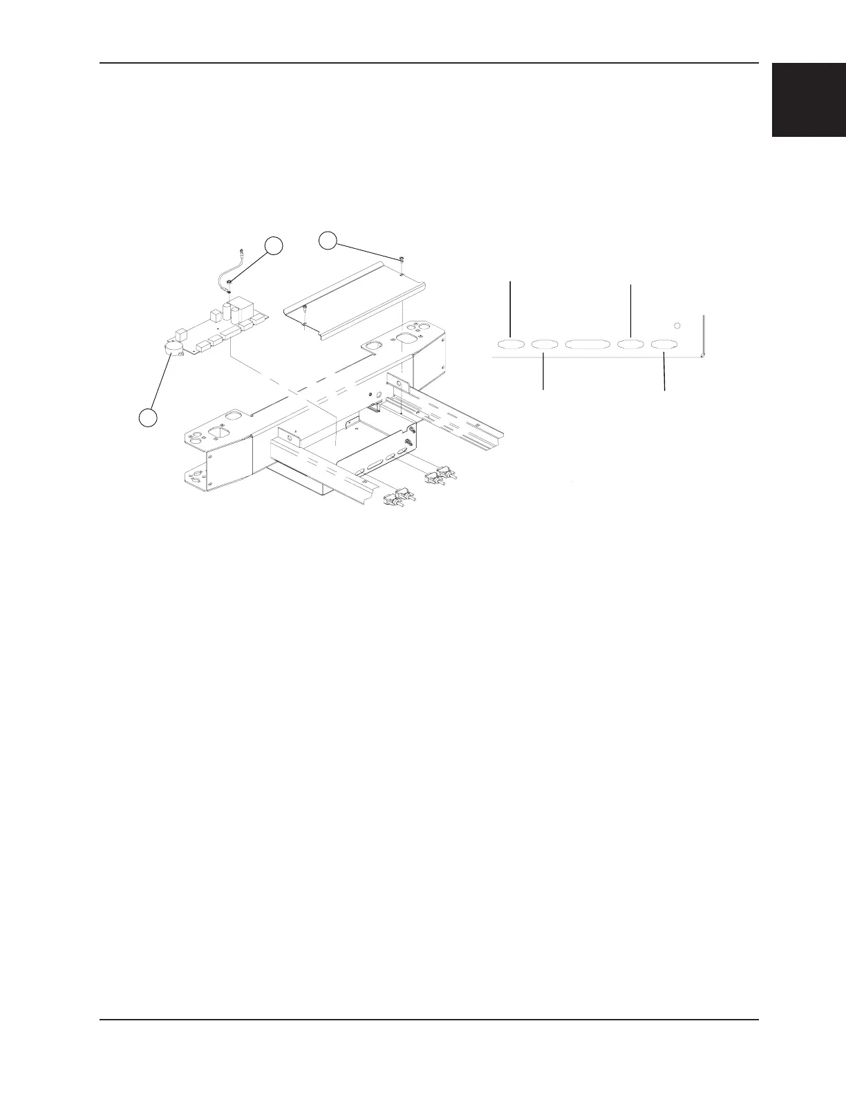
4. Using a #2 Phillips screwdriver, remove the two screws (A) holding the cover plate.
5. Properly ground yourself (see “Grounding Diagram” section).
To replace the Bed Exit Beeper, proceed with steps 6 to 9.
To replace the scale/bed exit board, proceed with steps 10 to 14
6. Disconnect the beeper cable from J3 of the control board.
7. Lift the beeper (B) to remove it from the plate. Remove any glue residue.
8. Reverse the above steps to install the new beeper.
9. Test the Bed Exit system to make sure the beeper operates properly.
10. Remove all cables connected to the control board. Note the cable locations in order to reconnect them correctly.
Refer to drawing OL280005L, page 1-76) for the connecting position of the cables on the scale/bed exit board.
11. Using a 3/8” combination wrench, remove the nut holding the ground cable to the scale board (B).
12. Using needle nose pliers, pinch the upper part of the stand-off pins and lift the defective board up and out.
13. Reverse the above steps to install the new scale control board.
Note
Be sure to reconnect the load cell cables on the scale/bed exit board in the proper order. Refer to Figure 13 when
reconnecting the load cell cables.
14. Calibrate the scale before returning the bed to service. Refer to the “Scale Calibration” procedure, page 1-55.
SCALE/BED EXIT BOARD/BEEPER REPLACEMENT (OPTIONAL)
B
A
CD
B
C
Head Right
Cell Cable
Foot Left
Cell Cable
Foot Right
Cell Cable
Head Left
Cell Cable
Figure 13
Service Information

 Loading...