1-44 280C-009-002 REV B www.stryker.com
Return To Table of Contents
English
HEAD END LIFT MOTOR REPLACEMENT
Note
In order to maintain the adjustment of the low position when replacing a lift motor, a special tool kit must be used. The kit
includes alignment fixtures. To obtain this kit, contact our Customer Service department and order part number KR0154.
Tools Required:
• Tool Kit KR0154
• Cutting Pliers
• #2 Phillips Screwdriver
• Small Regular Screwdriver
• 1/2” Combination Wrench
Procedure:
Note
When raising or lowering any of the litter
sections, ensure that all siderails are in the
highest position. Unless otherwise indicated, refer to Figure 10 for reference for this procedure.
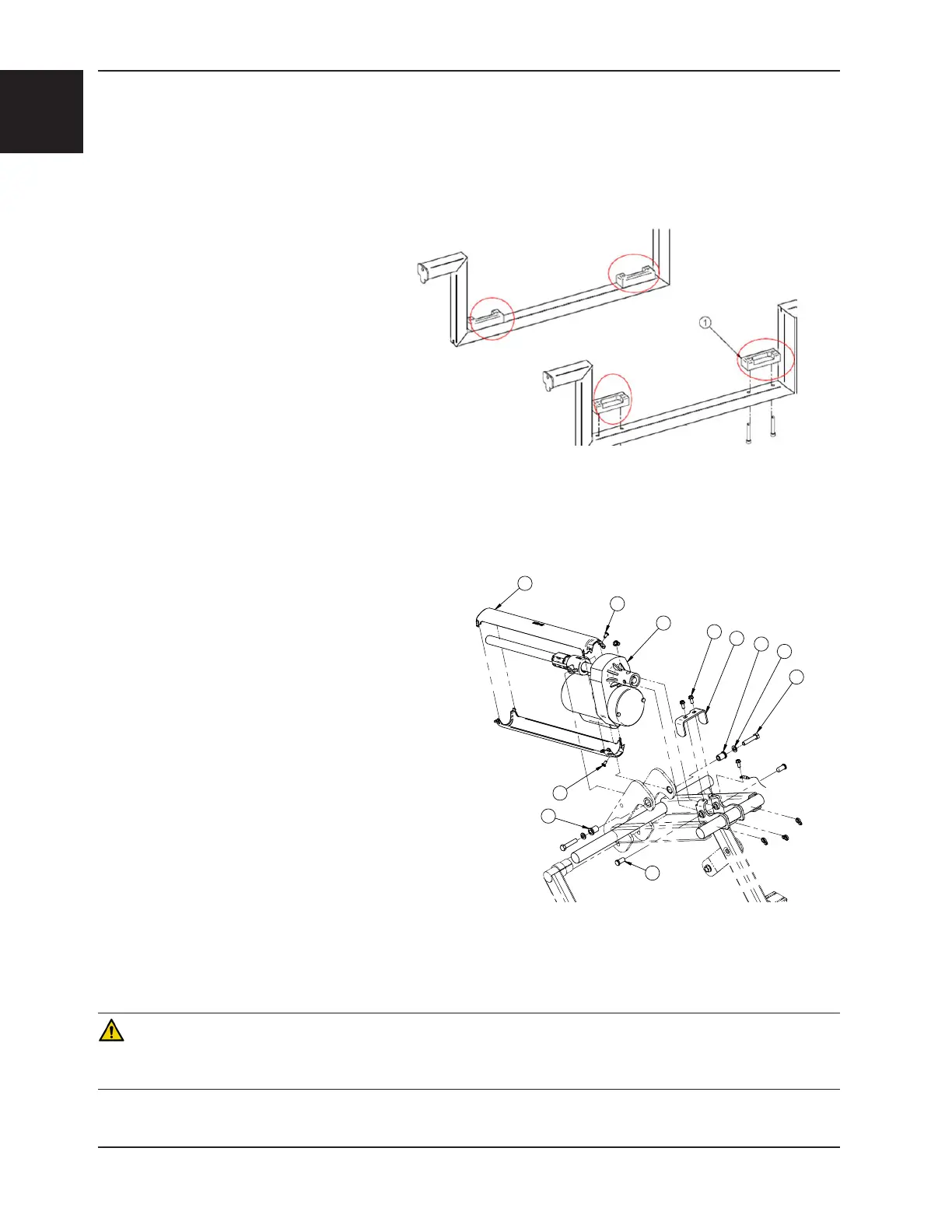
1. Install the alignment fixtures (KR0154) on both sides of the brake mechanism on the base frame, under the lower
fixed frame.
2. Lower the bed, until the lower fixed frame is completely supported by the U-shaped pieces of the fixture (see Figure 9).
3. Remove the headboard.
4. Raise the head section to about 45°.
5. Unplug the power cord from the wall receptacle.
6. Using cutting pliers, cut the cable ties holding the
defective lift motor power cord to the bed frame.
Then unplug the motor connector.
7. Using a 1/2” combination wrench, remove the two
bolts (D), two washers (C) and two shoulder spacers
(B) holding the molded nut support to the elevation
lever arm.
8. Using a #2 Phillips screwdriver, remove the two
screws (E) holding the actuator support cover (G) to
the head lever arm and remove it.
9. Remove the two pivot pins (H) holding the motor
(A) to the support. To ease the removal of the pins,
insert a small regular screwdriver into the opening at
the end of the motor and push out the pins.
10. Using a #2 Phillips screwdriver, remove the two
screws (F) holding the plastic screw cover (J) to the motor. Remove the plastic screw cover and install it on the
new actuator.
11. Reverse the above steps to install the new actuator.
CAUTION
The limit of the new motor must be adjusted prior to reconnecting it to the lift lever. An improper adjustment can damage
the lift mechanism.
Service Information
Figure 9
F
E
B
C
D
H
J
F
G
A
B
Figure 10
 Loading...