www.stryker.com 280C-009-002 REV B 1-33
Return To Table of Contents
English
FOOTBOARD CONTROL MEMBRANE REPLACEMENT
Tools Required:
• Small Regular Screwdriver
• #2 Phillips Screwdriver
Procedure:
1. Raise the bed to the highest position and apply the brakes.
2. Unplug the power cord from the wall receptacle.
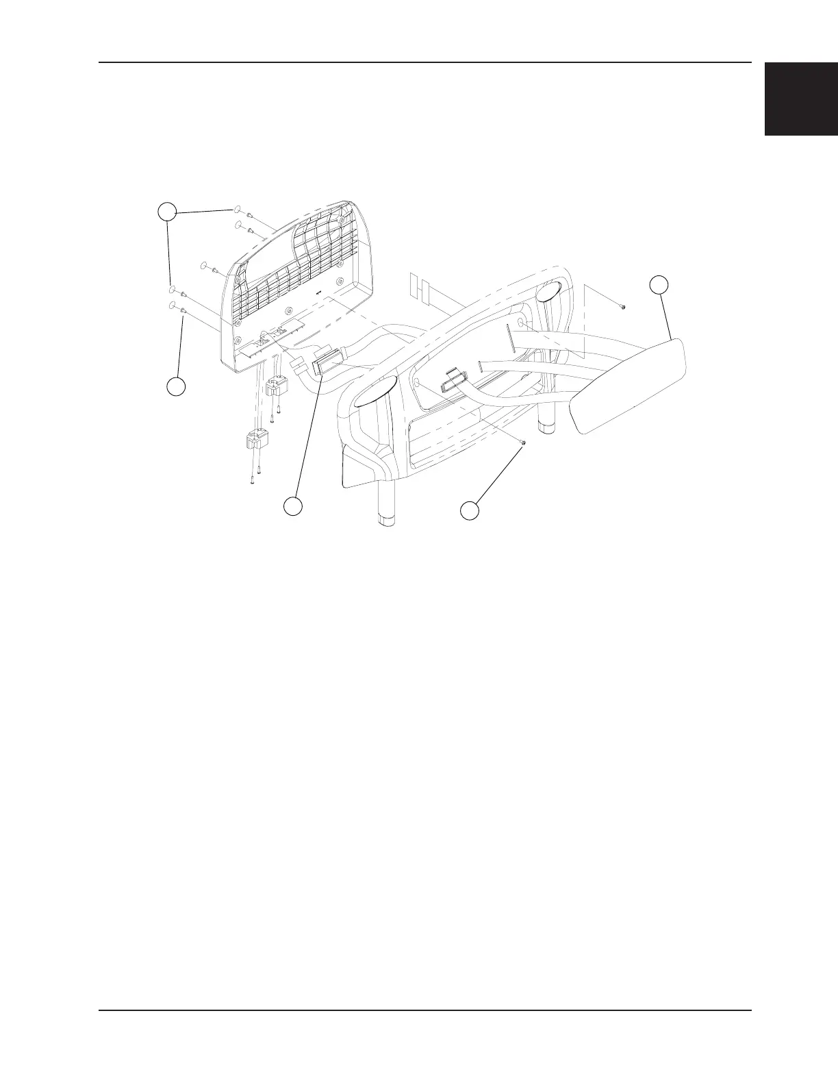
3. Using a small regular screwdriver, lift and remove the five round self-adhesive screw-covers (A) located on the foot
board cover and the self-adhesive membrane (B) of the foot board control panel to expose the screws holding the
cover to the foot board. Use caution when inserting the screwdriver under the membrane to avoid scratching the
plastic cover.
Note
Do not reuse the self-sticking parts removed since their self-adhesive coating considerably looses its efficiency once
they are removed. Replace them with new parts.
4. Properly ground yourself (see the “Static Protection Procedure”, page 1-13).
5. Using a #2 Phillips screwdriver, remove the seven screws (C) holding the cover to the foot board and remove the
cover after having removed the cables connected to it. Note the cable positions in order to replace them properly.
6. Remove the defective membrane.
7. Reverse the above steps to install the new membrane.
Note
Use caution to avoid adhering the cable to the back of the membrane.
8. Test all the functions of the foot end control panel before returning the bed to service.
B
C
C
D
Figure 5
Service Information

 Loading...