1-54 280C-009-002 REV B www.stryker.com
Return To Table of Contents
English
6. Using diagonal pliers, cut the two cable ties holding the defective cell cable to the frame immediately after the cell.
Repeat for the adjacent cell.
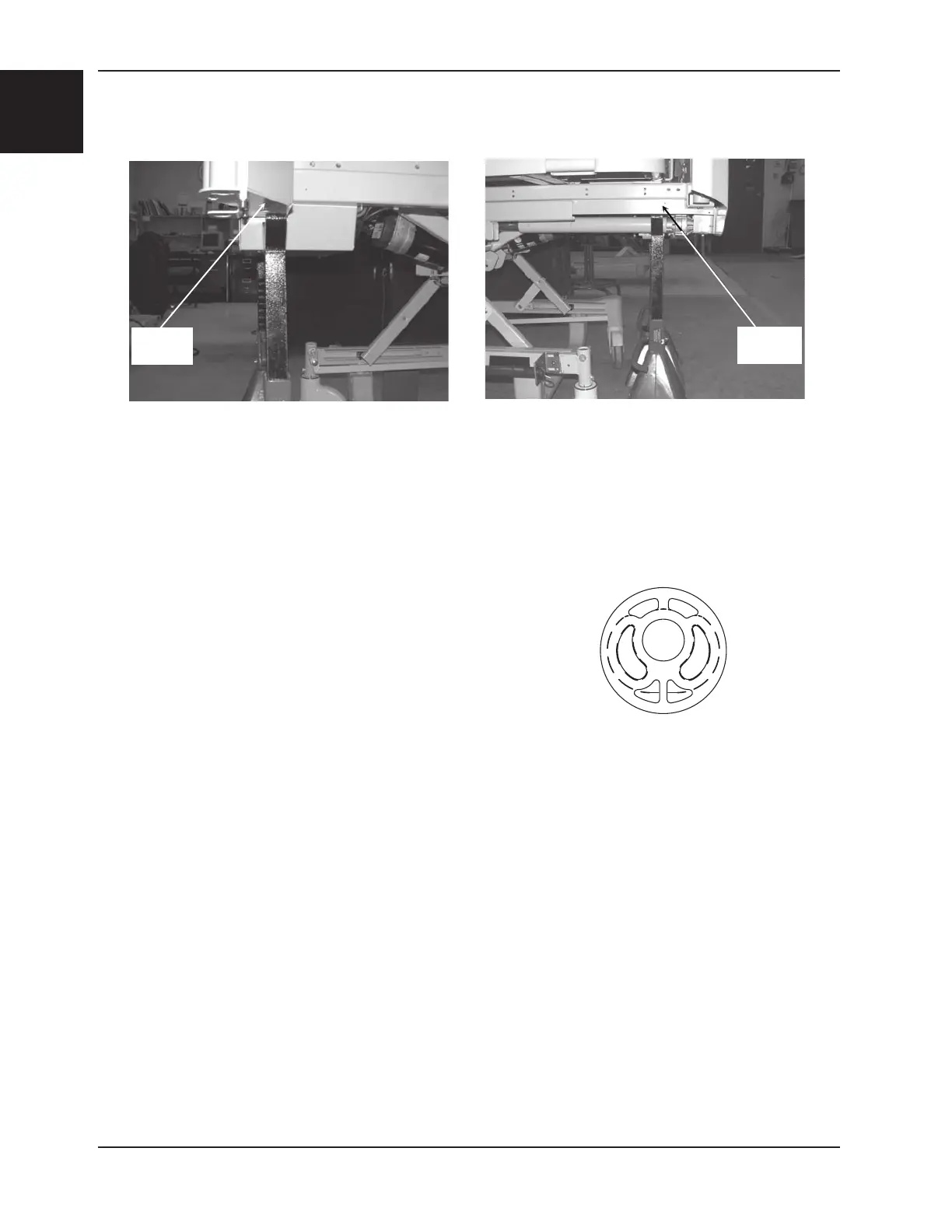
7. Lower the bed until the two Allen screws holding the defective load cells to the frame are easily accessible.
8. Unplug the power cord from the wall receptacle.
9. Using a 1/4” Allen wrench and a 1/2” combination wrench, remove the two nuts and two Allen screws (B) holding
the defective load cell to the frame.
10. Cut the cable ties holding the defective load cell cable the frame. Unplug the defective load cell cable from the
scale/bed exit board. Remove the defective load cell.
11. Inspect the elastomer sleeves (C) to ensure that the inner circular hole is not worn. Replace if necessary. Note the
orientation of the elastomer sleeves when replacing (see detail at right).
12. Reverse the above steps to install the new load cell.
13. Calibrate the scale before returning the bed to service. Refer to the “Scale
Calibration” procedure, page 1-55.
LOAD CELL REPLACEMENT (OPTIONAL) (CONTINUED)
Support
Point
Support
Point
Service Information
Proper elastomer
sleeve orientation.
 Loading...