1-10 Sun Netra T5220 Server Service Manual • January 2012
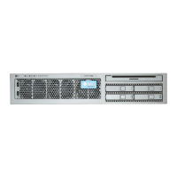
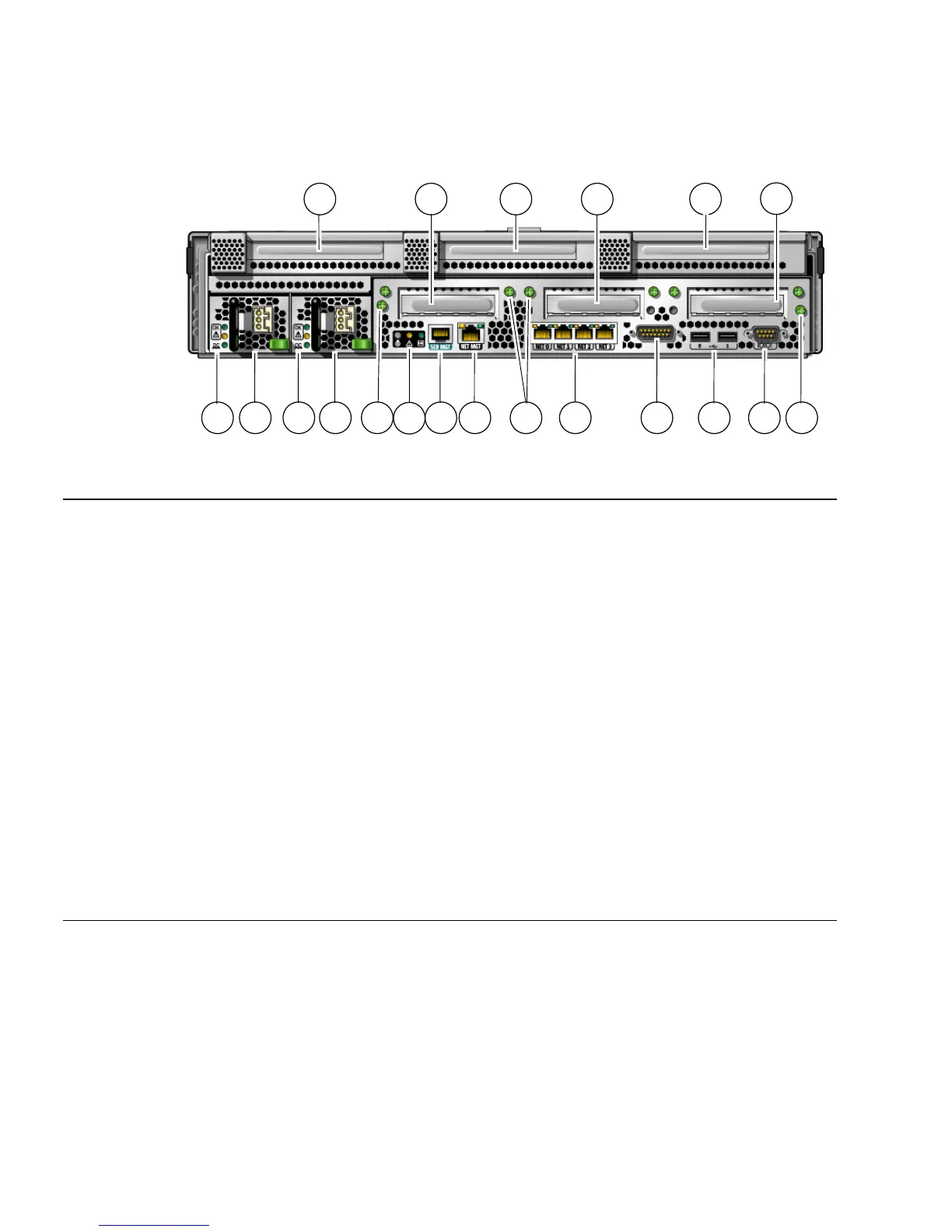
FIGURE 1-3 Rear Panel Connectors, LEDs, and Features on the Sun Netra T5220 Server
Figure Legend
1 Power Supply 0 LEDs top to bottom: Locator LED and
Button, Service Required LED, Power OK LED
11 Alarm Port
2 Power Supply 0 12 USB ports left to right: USB0, USB1
3 Power Supply 1 LEDs top to bottom: Locator LED
Button, Service Required LED, Power OK LED
13 TTYA Serial Port
4 Power Supply 1 14 Captive screw for securing motherboard (2 of 2)
5 Captive screw for securing motherboard (1 of 2) 15 PCI-X Slot 3
6 System LEDs left to right: Locator LED Button, Service
Required LED, Power OK LED
16 PCIe or XAUI Slot 0
7 Service Processor Serial Management Port 17 PCI-X Slot 4
8 Service Processor Network Management Port 18 PCIe or XAUI Slot 1
9 Captive screws for securing the bottom PCI cards. Note
that there are two screws on either side of each bottom
PCI card (total 6).
19 PCIe Slot 5
10 Gigabit Ethernet Ports left to right: NET0, NET1, NET2,
NET3
20 PCIe Slot 2
2 4 5
12 13
7 8
10
15 16 19
20
11 14
31 9
17 18
6