Chapter 2 Preparing for Service 2-13
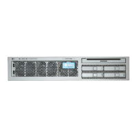
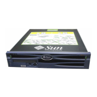
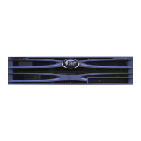
TABLE 2-1 Server FRU List
No. FRU Replacement Instructions Description FRU Name
*
1
Top Cover Section 2.3.5, “Removing the
Top Cover” on page 2-8
Requires a pen to remove. Does not power
off server when removed.
2
FB-DIMM/CPU
duct
Section 4.4, “Replacing the
Air Duct” on page 4-17
Aids cooling of FB-DIMMS and CPU.
3
System Fan
Assembly
Section 5.3, “Replacing the
System Fan Assembly
(FT0)” on page 5-6
Contains three fans for cooling the mother-
board assembly.
FT0
4
FB-DIMM Fan Section 5.5, “Replacing the
FB-DIMM Fan Assembly
(FT2)” on page 5-14
Single fan for cooling FB-DIMMs
5
LED board Section 5.7, “Replacing the
LED Board” on page 5-17
Contains the push-button circuitry and
LEDs that are displayed on the bezel of
the box.
LEDBD
6
Air filter Section 5.1, “Replacing the
Air Filter” on page 5-1
Cleans air before entering system.
7
Media bay
assembly
Section 3.3, “Replacing the
Media Bay Assembly” on
page 3-8
Bays that house hard drives and optical
media drive.
8
Optical media
drive
Section 3.2, “Replacing the
Optical Media Drive” on
page 3-6
Optical media drive DVD
9
Hard drives Section 3.1, “Replacing a
Hard Drive” on page 3-1
SAS, 2.5-inch 146 GB hard drives
The two HDD configuration includes a
removable DVD drive; the four HDD has
HDD2 and HDD3 in place of the DVD.
HDD0
HDD1
HDD2 HDD3
10
Power
distribution
board (PDB)
Section n, “Section 6.1.6,
“Powering On the Server”
on page 6-8” on page 5-22
Provides the main 12V power interconnect
between the power supplies and the other
boards.
PDB
11
Alarm board Section 5.6, “Replacing the
Alarm Board” on page 5-15
Provides dry-contact switching according
to alarm conditions.
12
Hard drive fan
assembly
Section 5.4, “Replacing the
Hard Drive Fan Assembly
(FT1)” on page 5-9
Fans that provide supplemental cooling of
the hard drives and optical media drive.
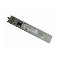
13
Power supplies
(PS)
Section 5.2, “Replacing a
Power Supply” on page 5-3
The 650W power supplies provide -3.3
Vdc standby power at 3 @ 3 Amps and 12
Vdc at 25 Amps.
PS0
PS1