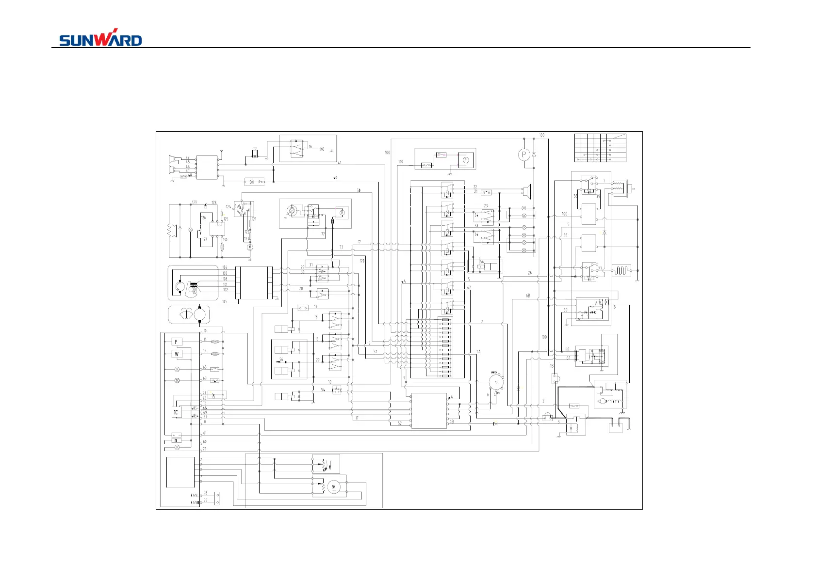
5.3.4 Circuit diagram
200
9
40
100
10
50
17
51
110
41
120
241
242
boom lamp
Headlamp
Gasoline pump
20A
20A
20A
Cigar light
15A
Auto idle speed
Wiper
10A
10A
Horn and
warning lamp
Solenoid valve
group
15A
15A
A/C system
20A
Monitor meter
10A
Engine control
10A
Standby power
15A
Indoor lamp
10A
Starter switch
10A
X0TERM01
X0TERM01
X0TERM01
X0TERM01
X0TERM01
X0TERM01
X0TERM01
X0TERM01
X0TERM01
X0TERM01
X0TERM01
X0TERM01
X0TERM01
X0TERM01
X0TERM01
X0TERM01
X0TERM01
X0TERM01
X0TERM01
X0TERM01
X0TERM01
X0TERM01
X0TERM01
X0TERM01
X0TERM01
X0TERM01
X0TERM01
X0TERM01
X0TERM01
X0TERM01
X0TERM01
X0TERM01
X0TERM01
X0TERM01
X0TERM01
X0TERM01
X0TERM01
Central
electric
control box
240
235
225
211
201
215
21
22
33
34
24
23
5
67
3
0
2
1A
220
230
210
15
4A
60
1413
12
11109876
5
43
2
1
Horn relay
Boom lamp relay
Head lamp relay
Standby relay 2
Standby relay3
Flameout control
relay
Standby relay 1
Warning lamp
9
1
10
5
2
6
Warning lamp switch
Option part:Warning lamp
(LH)
(RH)
+
-
+
-
6
4
5
7
Horn
(LH)
(RH)
+
-
+
-
Antenna
3
8
1
Cigar lighter
10W
Inside lamp
2
Mute
Wind speed switch
A/C amplifier
temperature sensor
Blower
Govern resistance
High/low pressure switch
Clutch
A/c
control
pannel
3
9
5
10
6
7
Scrubber control wire
Power(-)
Scrubber
generator(+)
Interval5s control wire
Reset wire
Reversed line
Positive rotation wire
Power(+)
Single control wire
Wiper controller
1
2
4
12
14
.
.
.
M
Wiper motor
M
Scrubber
1
2
11
12
DC12V
0V
485-
485+
PILOT
E/G STOP
BATTERY RELAY
GPS UNIT
5
6
8
7
9
10
3
START
4
High speed travel
solenoid valve
9
1
10
5
2
6
Break/Boom solenoid
valve
9
1
10
5
2
6
Dozer
blade/quck-change
solenoid valve
9
1
10
5
2
6
Option part:Switch valve group
High speed button of
dozer handle
High speed travel switch
Dozer quick change
switch
Breake and boom switch
Pilot cut off solenoid
valve
9
5
1
6
2
10
7
3
8
4
Wiper switch
9
1
105
Scrubber switch
Starter relay
A
B
Preheating
relay
DC12V-70A
Preheater
Fuel valve relay
DC12V-70A
1STime delay
module
HC0119
S
ON
P
E
Fuel control solenoid valve
DC12V-400W
Engine control box
HC0108
IC
A
STARTER
DC12V-3kW
B
C
27A
66A
12V 120AH
+ -
BATTERY RELAY
A
B
BR
E
60A
P
IG
L
60A
20A
2R
2RL
+
Option part:Fuel gasoline pump
2B
-
FUSE
Switch
Gasoline pump
100μF 50V
100μF 50V
motor-sw
motor
-
+
relay
Option part:Auto idle speed
FUSE
B
G
R
Platform
work lamp
HORN
Horn button
Platform
work lamp
Boom lamp of wane
switch
9
1
10
5
2
6
Boom lamp
Work lamp of wane
switch
9
1
10
5
2
6
Boom lamp
Cab top lamp
Cab top
lamp
Electric oil pump
30
50
17
19
58
STARTER
P
0(OFF)
I(ON)
II(HEAT)
III(START)
3058
1517
1950
Starter switch
b
a
+
+
Safety switch
Option:Flat cut
off solenoid valve
Option part :Auto idle
speed pressure switch
Option part
Option part
Charge
Air filter warnning
Air filter clogged
Water temperature
Water temperature sensor
Oil level
Oil level sensor
Monitor meter
Rev
Engine oil warnning
Preheating lamp
Engine oil pressure switch
301
Throttle
control IC
3
1
2
LOW
HIGH
Throttle drive
plate
2
3
5
1
4
300
302
0A
Throttle control
generator
306
304
Y
L
R
300
Program loading interface
1
2
Reversed line (blue)
Positive rotation wire (green)
Clockwise control wire(purple)
Anti-clockwise control wire(white)
Reset wire(brown)
1STime delay
module
Clockwise control wire
Anti-clockwise control wire