SV 977D User Manual - Appendixes
Table C.5.5. SP 75 interface description
PC RS 232,
9 - pin connector
Signal name
SP 75 connector
(DB 09 F)
Pin number
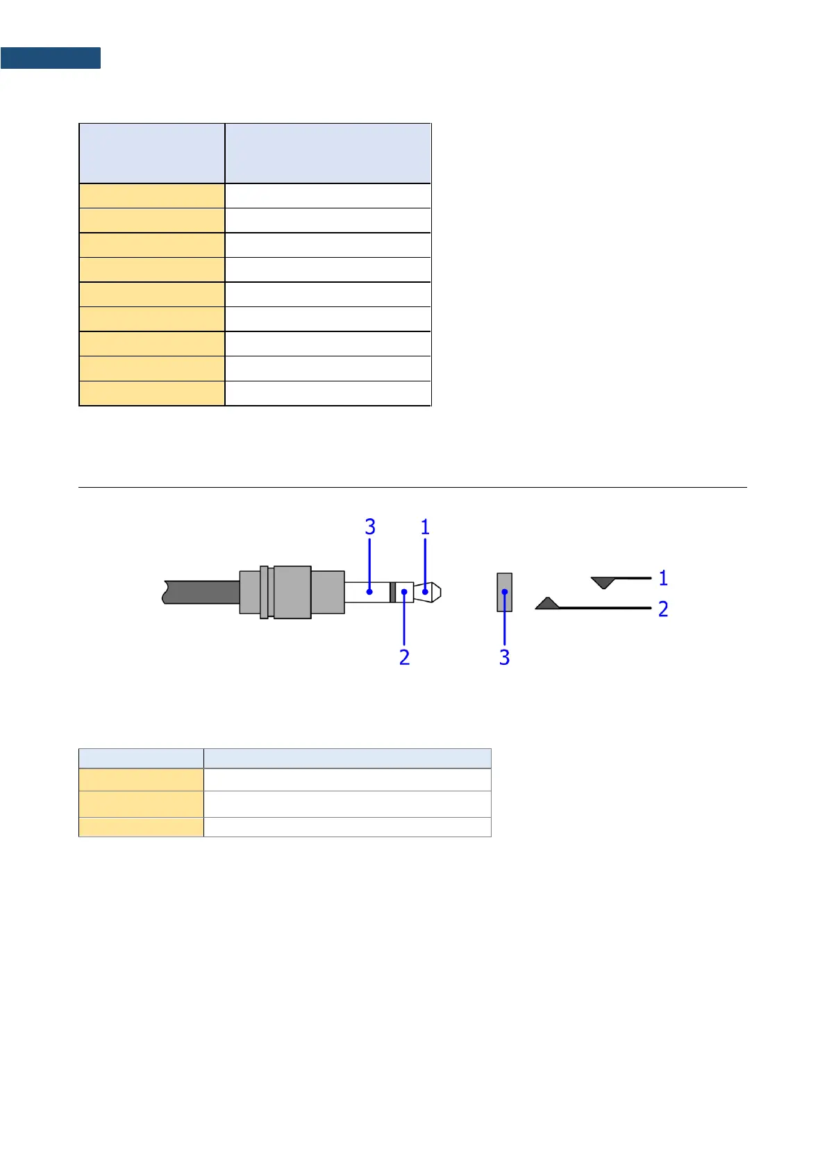
I/O – User programmable Analogue Outputs, Digital Input / Output connector
3.5 mm Mini Stereo Jack type (cable plug and instrument socket are shown)
Table C.5.6. Pin out of the 3.5 mm Mini Stereo Jack
Digital Input / Output
(*)
*depending on instrument set-up
The user may set-up the I/O mode in the screen <Menu> / Instrument / Multifunction I/O:
1. I/O Mode: Analog Out. When this option is selected, the measured signal from the selected channel is
fed to the terminal [1] of the I/O connector. Output voltage, frequency band and the output impedance are
following:
a) Output Voltage:
The output voltage is equal to 1.0 V
RMS
( 5 %) at:
● 120 dB indication of the instrument, on measurement range “L”
● 137 dB, indication of the instrument, on measurement range “H”,
when calibration factor is set to 0.0 dB.
b) Frequency Band (-3 dB): 0.02 Hz ÷ 40 kHz.
c) Output Impedance: 51 Ω / 5%
 Loading...


