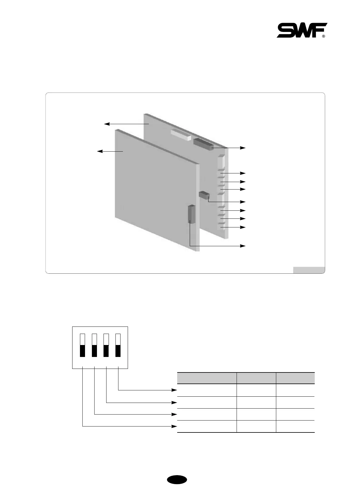
7.2.2 I/O Board, X/Y Driver Board Dip Switch Setting
<Fig. 7.2.2-1> shows the I/O, XY Driver Board of MC1 and MC2. For more information on the location of the board,
see “7.2.1 Rear Side of Control Box”.
XY Driver Board
I/O Board
I/O Board Dip Switch
[Fig.7.2.2-1]
X Driver Board Dip SW
XY Driver Board
I/O Board
X Driver Board Rotary SW1
X Driver Board Rotary SW2
X Driver Board Rotary SW3
Y Driver Board Dip SW
Y Driver Board Rotary SW4
Y Driver Board Rotary SW5
Y Driver Board Rotary SW6
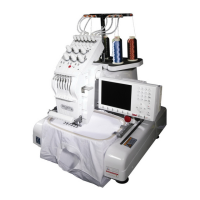
I/O Board Dip SW
Functions OFF ON
CAN I/D Setting
Reserved
Reserved
Reserved
MC1
–
–
–
MC2
–
–
–