V/D
S
ERIES
M
ECHANICAL ASSEMBLIES
Revision: 2.1 3-17
11 1312
14 16
15
17 1918
31 3332
34 3635
37 3938
41 4342
44
4645
47 4948
51 5352
565554
57 5958
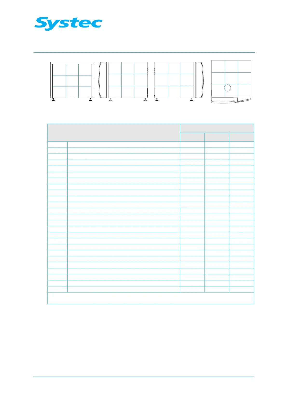
Fig. 4: D-45: Layout diagram of rear, right, left and top
Component
Position in layout diagram
DX DE DB
R12 No-return valve for external compressed air 14 14
R13 No-return valve for cavitation protection 35 35
S1 Sterile air filter 32 32 32
S2 Dirt trap sieve 49 49 49
SL1 Silencer for air compressor 14 14 14
SV1 Safety valve on steam generator 12
SV2 Safety valve for sterilisation chamber 12 12 12
Sw1 Pressure switch (7 bar) 19 19 19
Sw2 40 mbar switch 53 53 53
Y1 Steam inlet valve 38
Y2 Super Dry valve 38
Y3 Cooling water valve 35 35
Y4 Drain cooling valve (Cool drain) 47 47
Y5 Compressed air inlet valve 35 35 35
Y6 Atmosphere valve 52 52 52
Y7 Fast exhaust valve 48 48 48
Y8 Vacuum valve 49/42* 58
Y9 Air extractor valve 48 48 48
Y11 Blow-out valve for cooling coil 41 41
Y12 Vacuum breaker valve 35 35 35
Y13 Compressed air valve 41 41 41
Y14 Demineralised water inlet valve 38 38
Y15 Pump water valve for vacuum pump 39 39
Y16 Top exhaust valve 57 57 57
Y19 Demineralised water for reservoir container 17 17 (opt.)
* for exhaust filters
Tab. 4: D-45: Position in layout diagram