V/D
S
ERIES
M
ECHANICAL ASSEMBLIES
3-18 Revision: 2.1
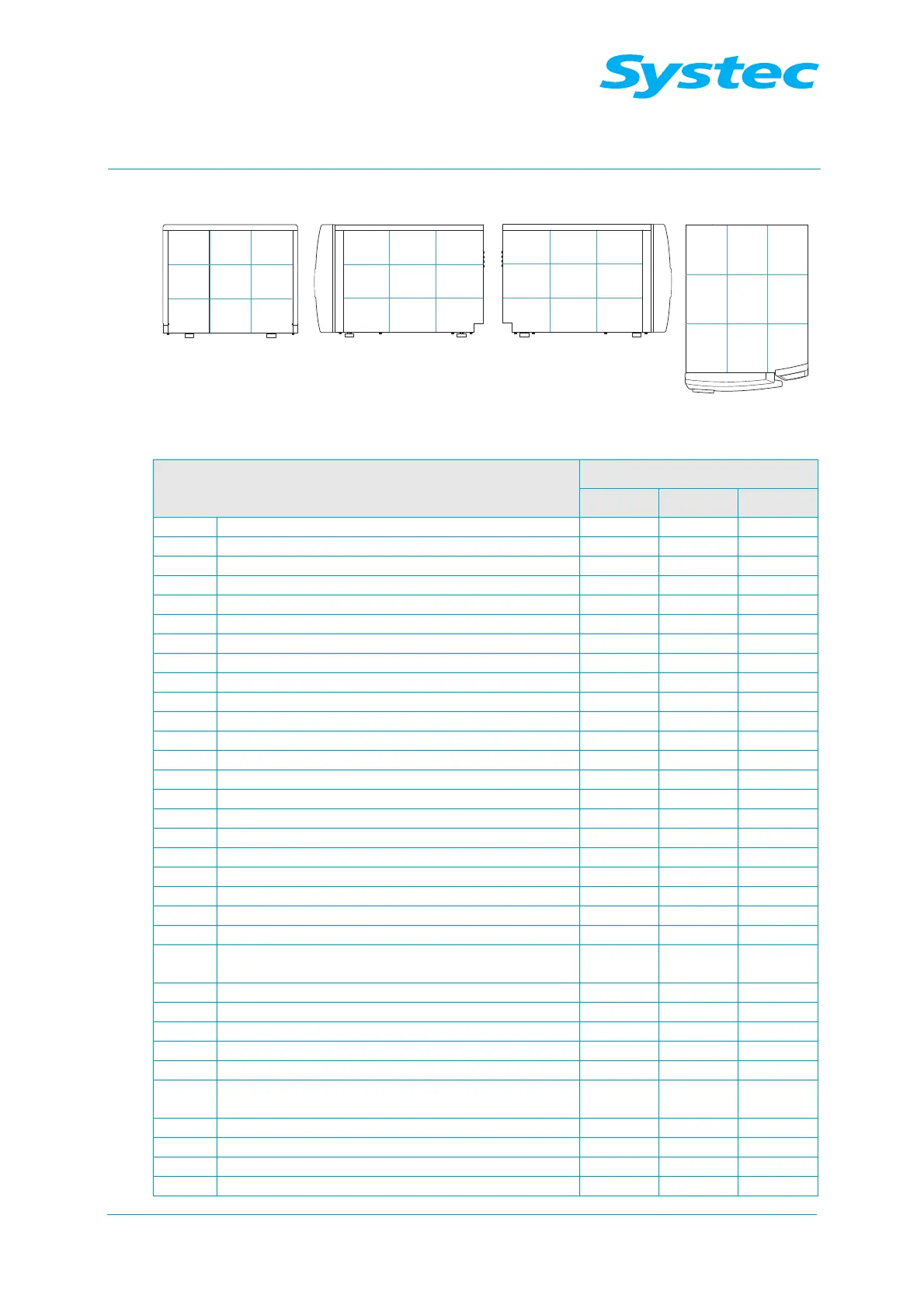
3.2.5 D-65 – 200
11 1312
14 1615
17 1918
31 3332
363534
37 3938
41 4342
464544
47 4948
51 5352
565554
57 5958
Fig. 5: D-65 – 200: Layout diagram of rear, right, left and top
Component
Position in layout diagram
DX DE DB
Steam generator 38/39
Pneumatic assembly 45 45 45
BV1 Manual drain tap for steam generator 17
D1 Steam air extractor for sterilisation chamber 48 48 48
D2 Steam air extractor (Super Dry) 48
F1 Demineralised water flow monitor 36
F2 Vacuum flow monitor 32 32
M1 Demineralised water feed pump 36 36 (opt.)
M2 Vacuum pump 34 34
M3 Air compressor 37 37 37
N1 Needle valve for air extraction 48 48 48
NR6 Needle no-return valve – “Blow out cooling coil” 45 45
NR7 Needle no-return valve for cavitation protection 34 34
P1 Manometer for external compressed air 32 32
P2 Manometer for internal compressed air 45 45 45
PR1 Pressure reducer for external compressed air 32 32
PR2 Pressure reducer for cooling water 32 32
PS1 Pressure transducer for steam generator 16
PS2 Pressure transducer for sterilisation chamber 45 45 45
PV1 Compressed air reservoir 45 45 45
PV2 Exhaust filter 57 57
R1 No-return valve for demineralised water 17 36
R2 No-return valve on pressure transducer for steam
generator
16
R3 No-return valve for cooling water 33 33
R4 No-return valve for compressed air inlet 52 52 52
R5 No-return valve for drain 48 48 48
R6 No-return valve for air compressor 45 45 45
R7 No-return valve for vacuum 48 48
R8 No-return valve for steam inlet (exhaust filter
option)
58
R9 No-return valve – “Blow out cooling coil” 35 35
R12 No-return valve for external compressed air 32 32
R13 No-return valve for cavitation protection 34 34
S1 Sterile air filter 35 35 35