V/D
S
ERIES
M
ECHANICAL ASSEMBLIES
Revision: 2.1 3-47
• Push the seals and plates apart above the spacer sleeves and
completely loosen the exposed screws (1), but do not take them out.
• Lift up the door cladding.
• Disconnect the cable to the control unit or printer, when necessary.
• Remove the door cladding.
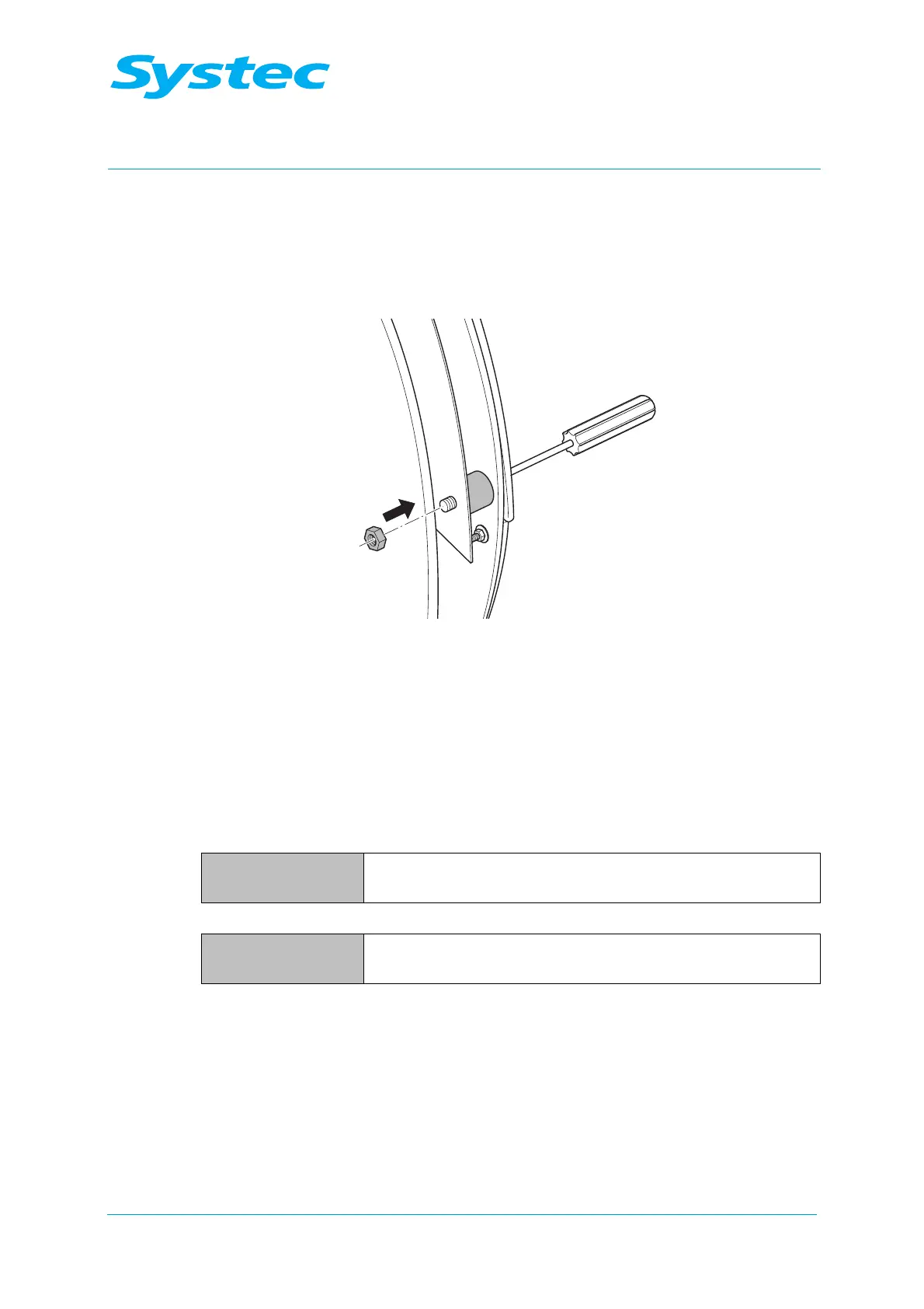
Fig. 25: Securing the screws using nuts
• Secure the 5 screws (M6) on the rear with nuts, when necessary.
• Tighten the fastening screws on the fixing plate again (see Fig. 23:
oben, pos. 1 and 2). Pay attention to the position of the door seal while
doing this.
V-40 – 55, D-23 – 45
V 40 – 55, D-45:
Necessary tools – 5 mm Allen key
– Slotted screwdriver
D-23:
Necessary tools – Phillips screwdriver
– Slotted screwdriver
• Remove the screen panel.
• Remove the fastening screws on the door cladding. Pay attention to
the position of the spacer sleeves while doing this.
• Remove the door cladding and disconnect any cables, when
necessary.