RUN MED: Service & Maintenance Manual - rev. 1.0
Page 6.10
(5) Check that the red LED H5, on the AT driver board is on.
(6)
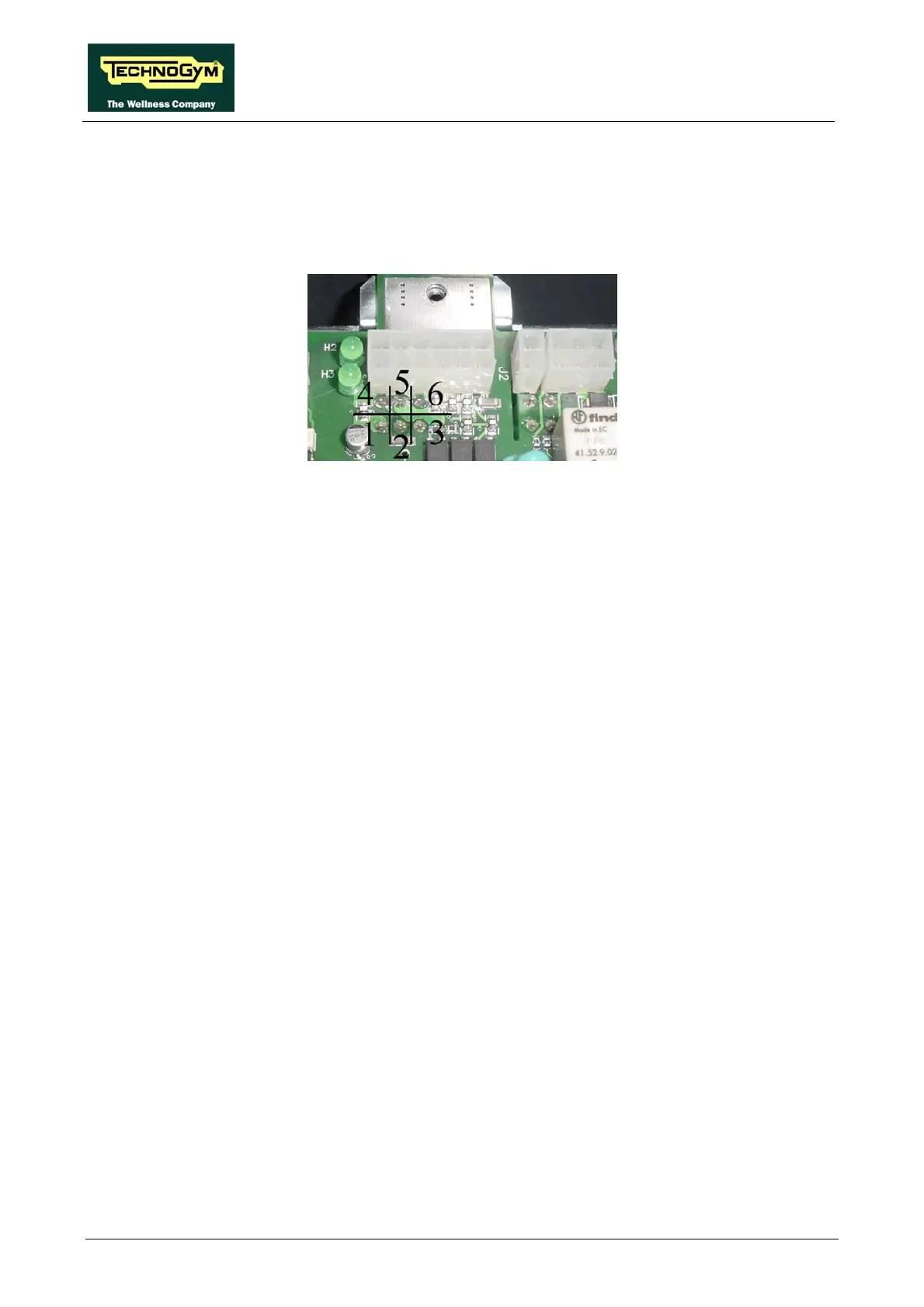
points 1-2 to measure the +12 Vdc signal and on 5-6 for the 5 Vdc
signal (see figure below).
Using a tester, check the voltages on the back of connector XU2 on the AT drive board,
placing the probes on test
Using a tester, check that all the output voltages +12 Vdc and +5 Vdc(7) on connectors J3 of the
AT driver board are correct, by referring to paragraph 2.7. “Wiring”.
) As for step (1) but on the patch connector C.
) As for step (7) but on connector CN7 of the display board ARM.
(8
(9