RUN MED: Service & Maintenance Manual - rev. 1.0
B
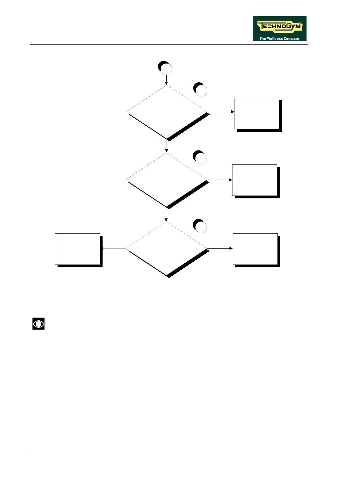
Are the DC voltages on patch
connector C correct?
Replace cable TRM-19
NO
8
Are the DC voltages at the
output of the AT driver
board correct?
Replace the AT driver
board
NO
YES
7
YES
Are the DC voltages at the
input to the display board
correct?
Replace the display
board
Replace cable TRM-20
NO
YES
9
Follow the procedure step by step to correctly diagnose the problem. Take particular care with the
checks highlighted by circled numbers, which are described in detail below:
To speed up the troubleshooting procedure, check the state of the power indicator LEDs
on the various circuit boards.
(1) Slightly lift the Faston connectors on the machine power inlet socket. Place the tester probes
across the live and neutral pins on the same connector. The measured voltage should be
approximately 220 VAC.
) As for step (1) but across the input of the circuit breakers. (2
) As for step (1) but across the output of the circuit breakers. (3
(4) Unplug the cable coming from the mutual inductance, from the connector J1 on the AT driver
board. Place the tester probes on the same connector. The measured voltage should be
approximately 220 VAC.
Page 6.9