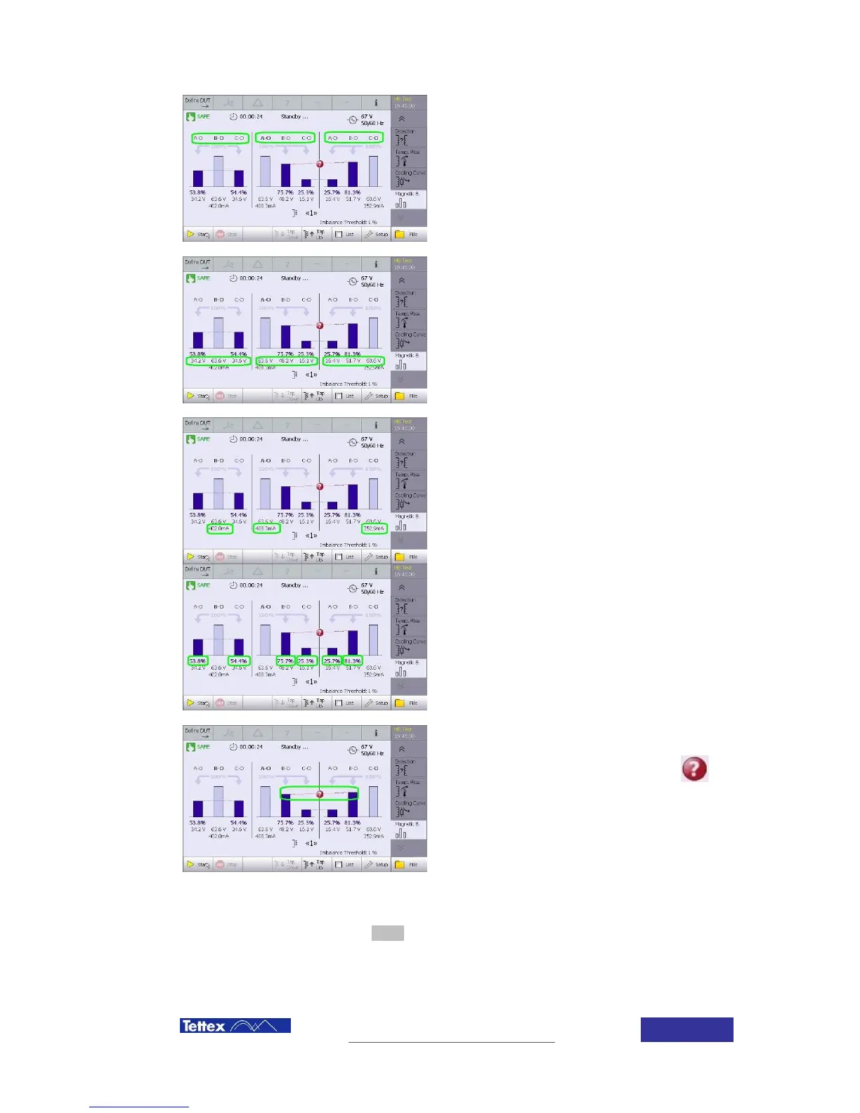
Connection shows the energisation and
measurement connections used in the test.
Each limb of the transformer is sequentially
energised and then the other limb voltages are
measured.
Highlighted area shows the voltage of the energized
limb and the voltage measured on the other limbs.
The energisation current for each limb of the
transformer is shown.
The percentage of the energisation voltage
measured in each of the other two limbs.
Voltage results which exceed the imbalance
threshold value are highlighted in red. The
corresponding measurements display the
symbol.
Measurements will be automatically saved after each test. Data storage options can be selected
in the Data folder, clicking in the setup button of the function key bar.