3 Theory
3.1 General Resistance Measuring Principle
Basically the instrument consists of 3 programmable power supplies, which can operate in
constant current or constant voltage mode. Further, these power supplies operate in two
quadrants. This means that a power supply can act as an active load, which is used to quickly
discharge the current from high inductive DUT.
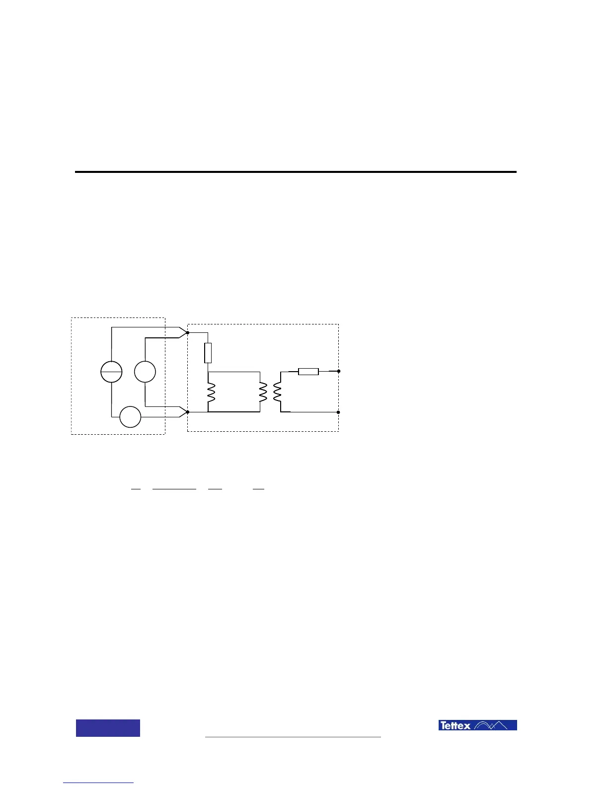
To determine the resistance of the DUT, the device uses 2 voltage and 2 current measuring units.
This way the unit can measure 2 different resistances with individual currents at the same time.
The resistance is calculated according to the principle described in the figure below: