Heat Run - Temperature
Rise
With these arrows you can toggle trough the single probes
definitions without closing this dialog window.
The temperature settings are common for the Temperature Rise and Cooling Curve functions
Liquid cooled transformers will use the
ambient, oil, rad. top and rad. Bottom
positions.
Dry type transformers are likely to use the
ambient, winding and core positions.
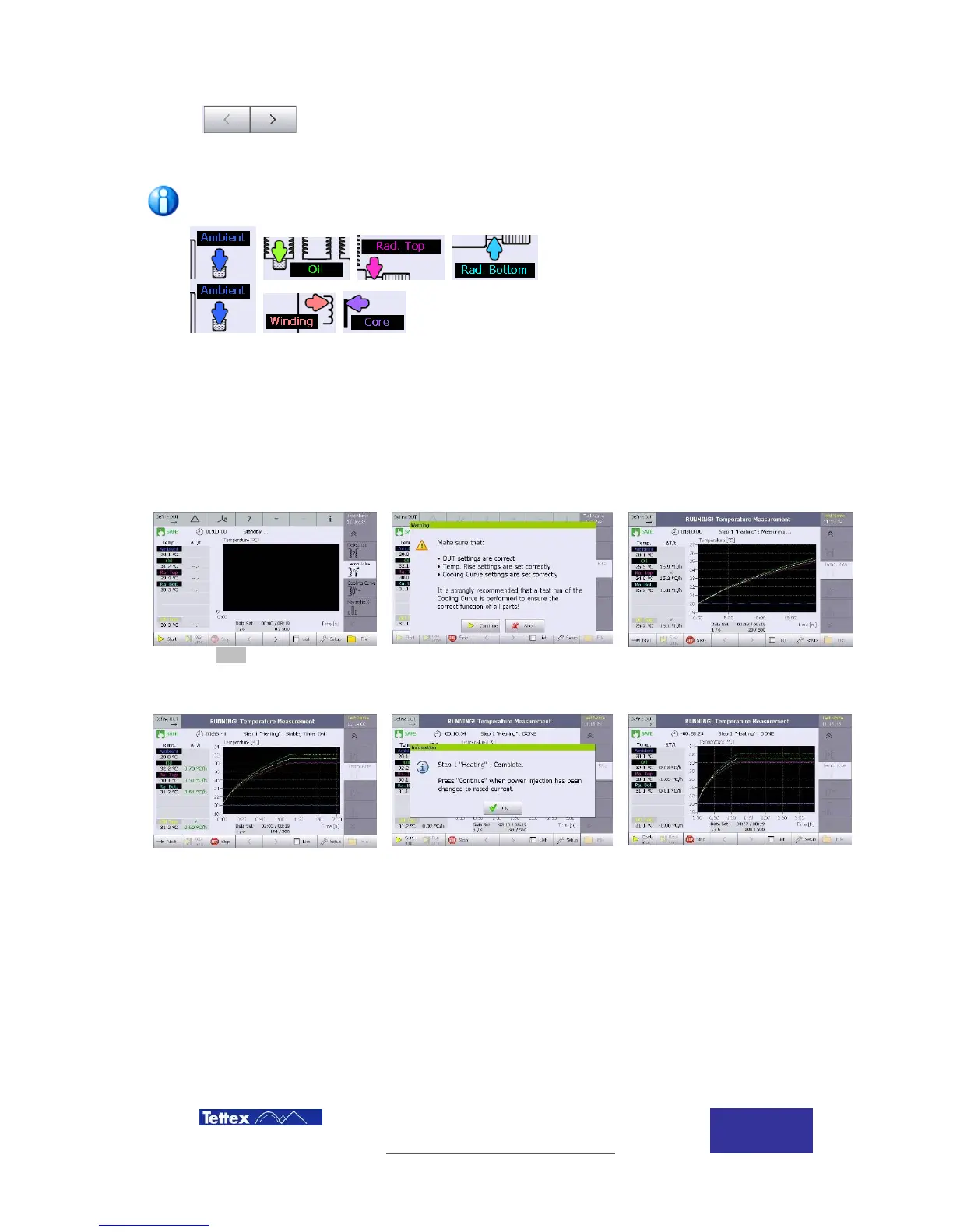
10.3.4 Liquid Cooled Transformer Measurement
Measurement consist of three steps, start the test when total loss injection is applied to the
transformer and then press continue after the total loss phase is completed and the HV supply is
reduced to rated current injection. Finally continue to the cooling curve application before the HV
supply is switched off.
Click Start for temperature
recording to begin when total loss
injection is applied.
A warning message is displayed
as a reminder that temperature
rise and cooling curve must be
setup before clicking Continue
The latest readings are shown on
the screen and the graph shows
all the measurements from when
the test was started.
When the temperature rise
reaches the setup value the
status changes to green and the
phase 1 timer starts to
countdown. If the setup value is
exceeded, the countdown will
reset
When the temperature rise has
been maintained for the required
time, the total loss injection is
complete. Click OK to start the
next phase of the test.
Apply the rated current injection
and then click Continue to start
phase 2 of the test.