8 Demagnetization
8.1 Theory
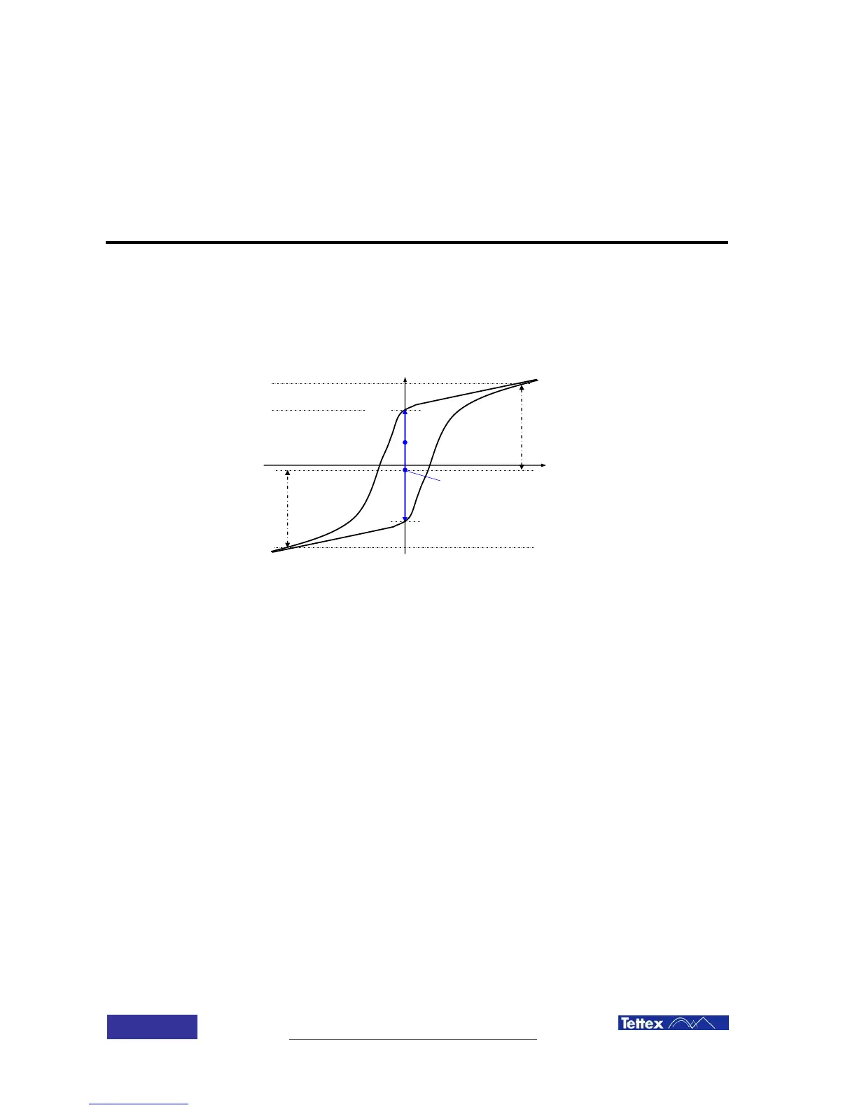
After disconnecting a transformer from the grid or performing a winding resistance measurement
with direct current, the transformer core will be magnetized. The following figure shows a
transformer core hysteresis curve with a possible magnetization M
0
. M
0
can be anywhere on the
y-axis within the hysteresis loop.
The magnetization M
0
can influence various measurements like turns ratio or frequency
response. For these measurements the magnetization should be M
0
≈ 0 Am
-1
, otherwise the
results can be wrong or not comparable. Further, connecting a magnetized transformer to the grid
can cause high inrush currents.
The common method to demagnetize a transformer core is to apply nominal AC voltage to the
transformer and slowly decrease its amplitude to zero. But this method requires a very large and
not portable controllable AC voltage source.
With the 2293 demagnetization function, the hysteresis loop of the transformer is calculated using
a special algorithm, later using an iterative procedure running in several cycles the
demagnetization status is reached