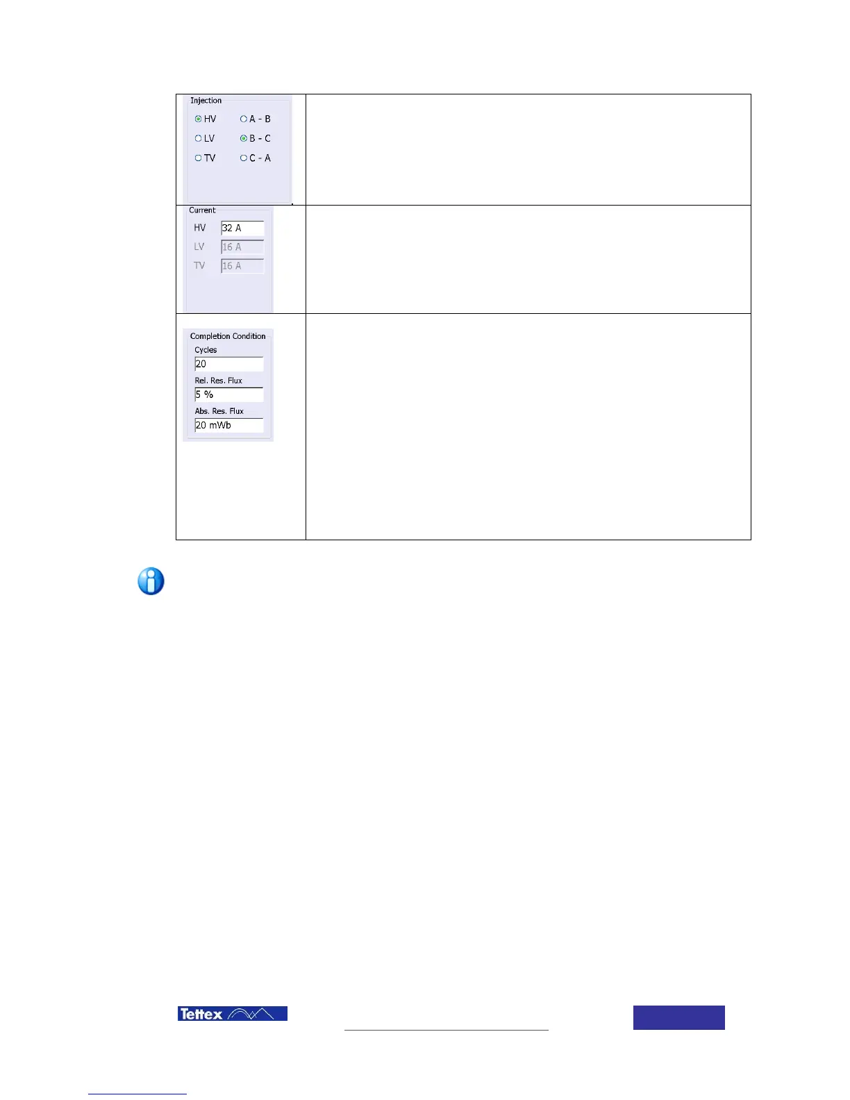
Injection Phase and Winding
Selection of winding and phases to be used for the demagnetization.
It is recommended to use the high voltage side and the center limb of the
transformer.
Current used during the demagnetization.
It is recommended to use at least 2 times the no load losses current of the
transformer of the winding used
Stop criteria to determine when a demagnetisation run will be completed:
Cycles
Maximum number of cycles the instrument will perform. Set this parameter
high enough (>50) to prevent abnormal termination
Relative Residual Flux
Percentage of the initial maximum magnetic flux that will declare the
transformer as demagnetized. Select low values for good demagnetisation
results.
Absolute Residual Flux
Maximum flux value in Weber (1Wb = 1Vs) that will declare the
transformer as demagnetized Select low values for good demagnetisation
results. 20mWb represents the lower technical limit of the device.
The demagnetization iterations will be completed, if any of the above
conditions is fulfilled.
If the Rel.Res.Flux is set to 5% (e.g. 30Wb x 5% = 1500mWb), the unit does usually stops
based on that higher value. Instead at its technical limit (Abs.Res.Flux) of 20mWb.