Premier Elite Series Installation Manual Installation
INS176-15 11
19: Com Port 1
Com Port 1 is a serial communications port and can be used for
connecting a PC running Wintex or any supported serial device to the
control panel (see page 101 for details).
20: Tamper Disable Link
This can be used to disable the box tamper when working with the
box lid removed.
21: Load Defaults Button
Press and hold this button whilst applying power to the control panel
to load the factory default settings. Press and hold this button for 7
seconds with power already on the panel to restore just the Engineer
code to the factory setting of
1234
. See page 53
for full details.
Loading the factory defaults can take up to 30 seconds to
complete.
Loading defaults will only be possible if the NVM has not been
locked (see page 71 for details).
For a complete list of factory defaults, see the Quick
Reference Guide section of this manual.
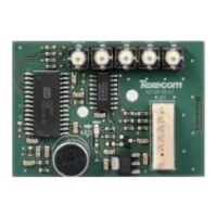
22: Expansion
The Expansion Port can be used for connecting a 60XiD Zone
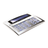
Expander (see page 33 for details) or an AV Module (see page 42 for
details), X-10 Module (Obsolete), Speech Module or a Memory
Module.
23: Heartbeat LED/Power Light
Flashes steadily to indicate that the control panel is functioning
correctly. If the light is ON or OFF all the time, then there could be a
problem (see page 48 for details).
24: Battery Charge Current Selector
When using a 7Ah standby battery the charge current selector should
be set to 300mA. If a 17Ah battery is connected (metal cabinet only)
the selector should be set to the 750mA position.
25: Engineers Keypad
A portable Engineers keypad can be plugged on here to allow easier
access for programming and testing.
When using a keypad as an Engineers keypad, the address
must be set to ‘10’ (see page 23 for details). The keypad zones
and lid tamper are not monitored.
F1 – F6: Protection Fuses (electronic PTC)
The following fuses are provided:
• F1 (900mA) Auxiliary 12V Power fuse (electronic PTC)
• F2 (900mA) Digicom Power (electronic PTC)
• F3 (900mA) Network 1 fuse (electronic PTC)
• F4 (900mA) Bell/Strobe fuse (electronic PTC)
• F6 (1.6 Amp) Battery fuse (electronic PTC)

 Loading...