Premier Elite Series Installation Manual Installation
INS176-15 35
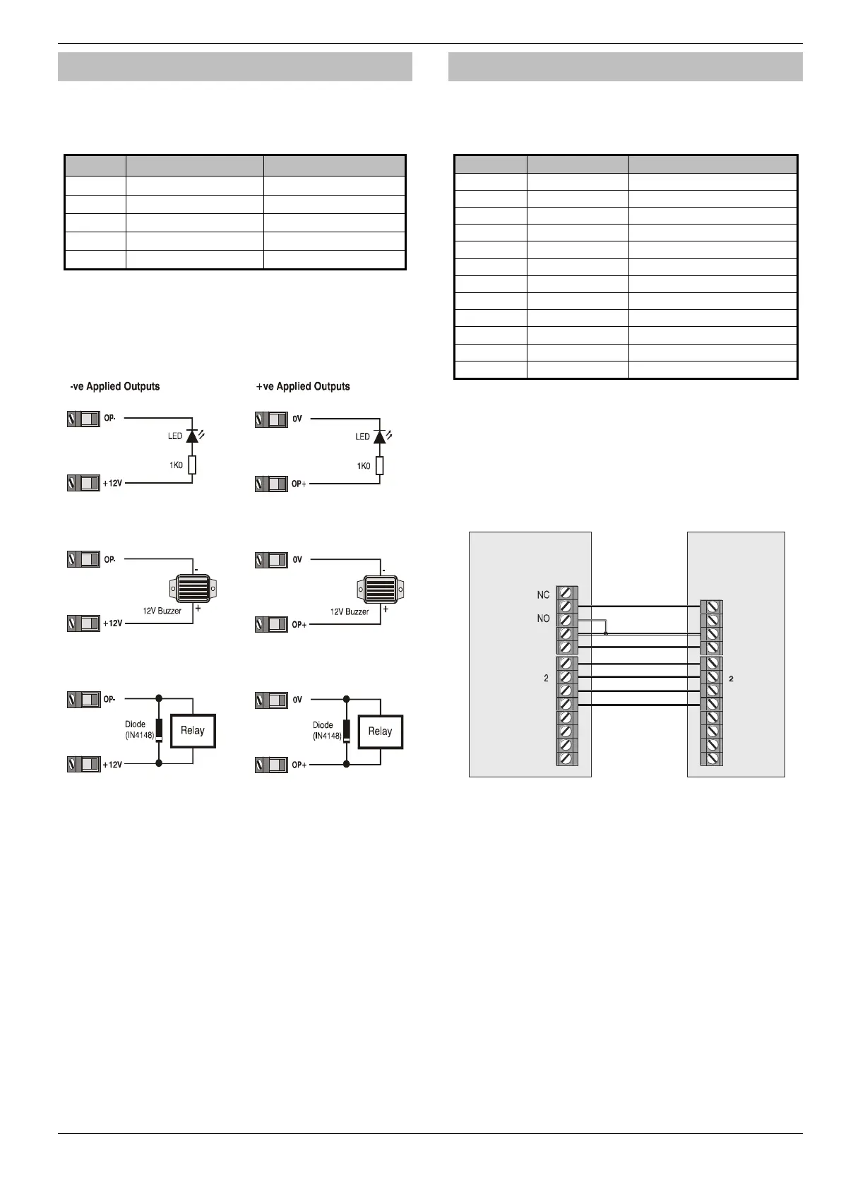
Panel Outputs
The control panel has five programmable outputs, which can be used
to drive auxiliary devices such as LED’s, sounders or relays etc. (see
page 83 for details). The table below shows the electrical
characteristics for each output:
** 88/168 & 640 only
Wiring Outputs
The diagram below shows some typical wiring examples:
For details on testing outputs, see page 129
Digicom Outputs 1 - 8
The control panel has eight programmable outputs, which can be
used for connecting to a stand-alone communicator (see page 84 for
details). The table below shows the electrical characteristics for each
output:
12V applied = Line Fault *
* Control Panel Line Fault Input (L/M)
In accordance with BSIA form 175, the line fault input on the control
can detect a single or a dual line fault for use with the ATS Remote
Test output type
Wiring a Stand Alone Communicator
The diagram below shows a typical wiring example:
For details on testing the digicom outputs, see page 129
Control
Panel
Power
1
3
4
5
6
7
8
12V
0V
Stand Alone
Communicator
C
DC +
L / M
R / R
DC -
1
3
4
5
6
7
8
Channel Inputs
Programmed
as Positive
Removed
Line Fault
Digicom
Outputs

 Loading...