Premier Elite Series Installation Manual Installation
INS176-15 27
Never set two expanders on the same network to the same
address.
* 24/48/64/88/168/640
** 48/64/88/168/640 only
*** 88 168 & 640 only
Expander Zones
The expander has eight programmable zones (see page 32 for wiring
details). Each zone is also fully programmable (see page 54 for
details).
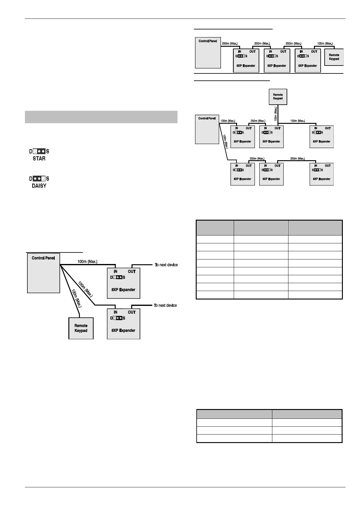
Star and Daisy Jumper Option
The PCB has a jumper JP3 which allows you to select either STAR
(S) or DAISY (D) wiring configuration. The jumper should be set as
follows:
If the network IN connection is wired in parallel with any other
device the jumper MUST be set to the S position. All previous
versions of the expander operated in this mode and for
backward compatibility the unit is supplied with the jumper in
this position.
If the network IN connection is only wired to one device the
jumper should be set to the D position.
When the jumper is set to the STAR position the network data signals
are not boosted between expander and the previous device. In this
mode the network cabling MUST not exceed 100m between devices.
When the jumper is set to the DAISY position the network data
signals are boosted between the expander and the previous device.
This mode will allow expanders on the network to be connected up to
250m apart and MUST only be selected if the expander has one
device connected to the network “IN” connections.
Star wiring example
Daisy chain wiring example
Combined Wiring example
Zone Numbering (24/48/88/168)
The table below shows the zone allocation when the expanders are
installed:
Network 2 can only be used on the 168.
For 640 see page 31
* 24/64/48/88/168/640
** 48/64/88/168/640 only
*** 88 168 & 640 only
Expander Auxiliary Input
The expander has one programmable input. This auxiliary input can be
used to monitor auxiliary devices such as tamper loops etc. Wire as per
Aux Tamper shown on page 33 (see page 82 for details). The system
will respond as follows:
For further details on how the input status affects the system
please refer to page 82.
* For wiring details, see page 36.

 Loading...