Premier Elite Series Installation Manual Installation
INS176-15 37
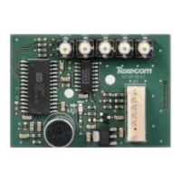
Plug-on Communicators
The Com300 is a multi-format 8-channel digital communicator/300-
baud modem for use with a standard analogue telephone line.
The Com2400 is a multi-format 8-channel digital communicator/2400-
baud modem for use with a standard analogue telephone line in
addition, this modem can also send Short Message Service (SMS)
text messages to a mobile phone.
These Communicators can be used to report system events to an
Alarm Receiving Centre using Fast Format, Contact ID or SIA Level II
or to upload/download control panel information using the Wintex UDL
software and a PC.
Plugging on the Communicator
Ensure that the board is the correct way up (see below). Locate the
plug into the communicator socket on the control panel and line up
the mounting holes with the pillars in the base. Once all the holes
line up, press down gently until the pillars snap into the holes.
12-W/24-W & 48/64-W Connection
Carefully lift the control panel PCB and fix the COM unit into the
space provided with the connection lead attached.
The red lead should be positioned on the uppermost pin of the
COM unit.
The control panel end of the connector should be attached with the
red lead on the left most pin of the digi modem connector.
Standard Telephone Line Connections
A standard telephone line must be connected to the Com300 or
Com2400 communicator as shown below:
ComPort+
The Premier Elite ComPort + plugs into the onboard digi connector
on Premier Elite 12/24/48/64/88 & 168 control panels allowing use
of Com Port 3.
Premier Elite 640 already has Com port 3.
V3 firmware is required to enable the device, which when used
allows connection of any device listed in the Com 3 dropdown
menu, or connection to a local PC via a USBCom for
upload/download capability.
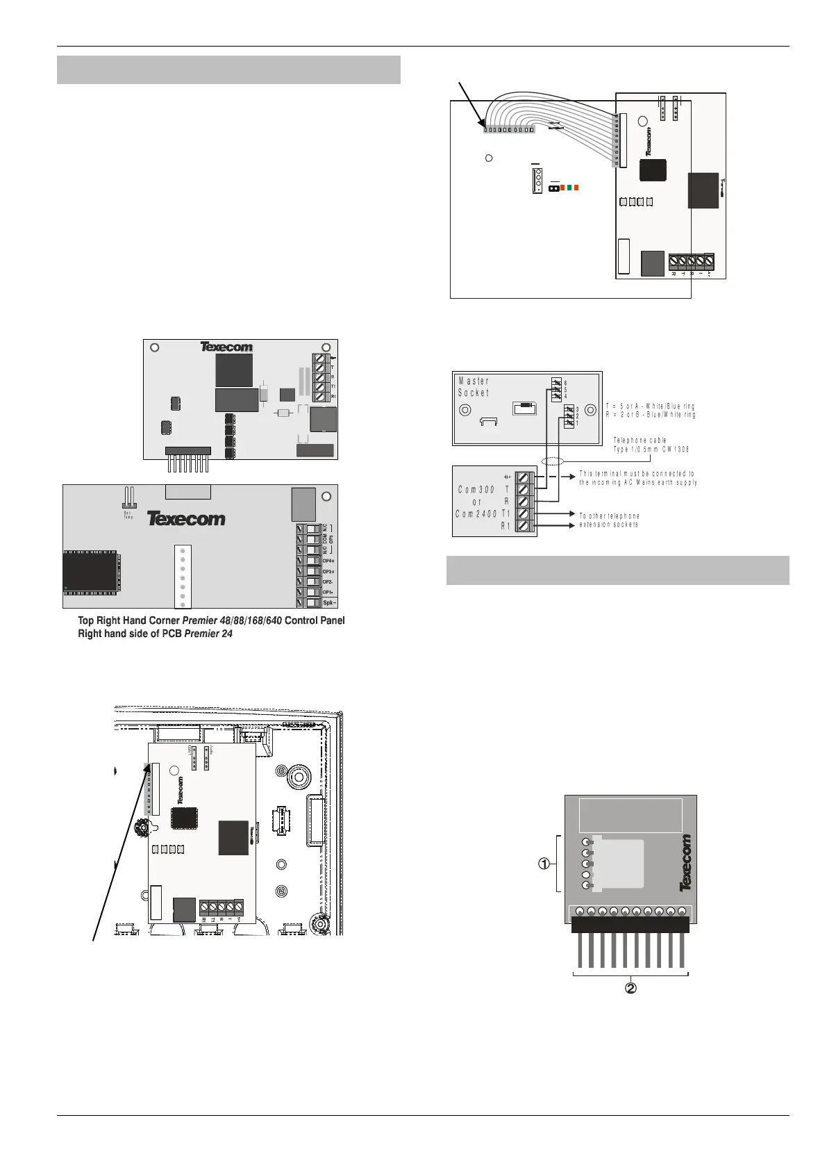
PCB Layout and Connections
The figure below shows the PCB layout of the Premier Elite
ComPort +

 Loading...