Installation Premier Elite Series Installation Manual
34 INS176-15
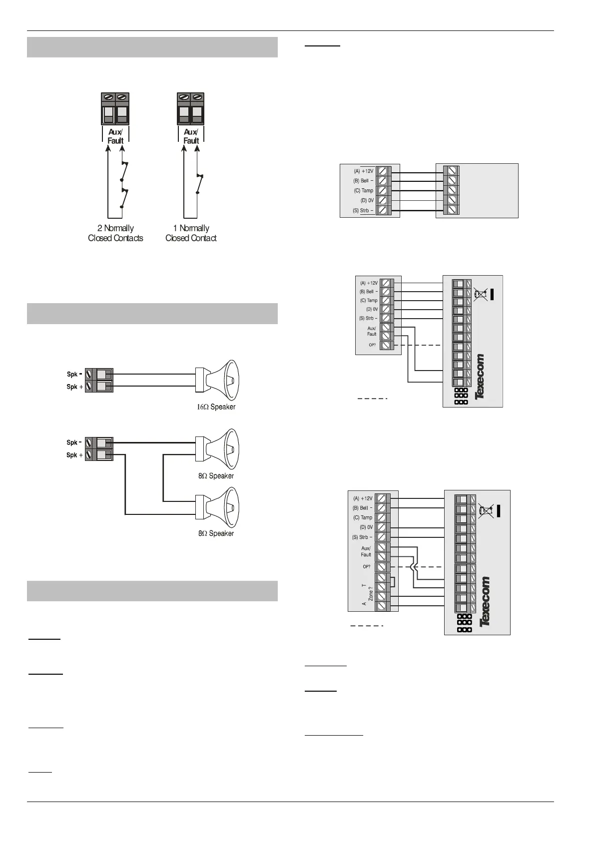
Auxiliary/Fault Connections
The Aux/Fault terminals allow the control panel to monitor the tamper
& fault loops of external devices such as power supplies etc.
If the ‘Aux/Fault’ terminals are not being used they must be
linked out.
Speaker Connections
This output can be used for driving up to one 16 or two 8
loudspeakers as shown below:
For details on testing Speaker outputs, see page 129.
External Sounder Connections
The following terminals have been provided for connection to an
external sounder:
(A)
+
12V
12V supply (protected by a 1A fuse F4). Normally connected to
‘+12V’ on the sounder.
(B) Bell –
Sounder output, switches to 0V in alarm (SAB) and is rated at 500mA.
Normally connected to Trigger -ve on
the sounder. This output can also be programmed for SCB operation (see
page 70 for details).
(C) Tamp
Negative tamper return. Normally connected to ‘Tamper Out’ on the
sounder. If this terminal is not being used, it must be connected to
‘0V’.
(D) 0V
0V supply. Normally connected to ‘0V’ on the sounder.
(S) Strb –
Strobe output, switches to 0V in alarm and is rated at 500mA.
Normally connected to strobe -ve on the sounder (where applicable,
connect the strobe +ve to +12V).
For EN50131 & INCERT installations the Bell & Aux Tamper must be wired to
a zone.
Grade 2 Installation
Grade 3 Installation
The Aux/Fault relay should be programmed as Fault
Grade 3 Installation (Using a Zone)
Aux/Fault –
Wire the Sounder Tamper Relay to these terminals
Zone ? –
Wire the Sounder Fault Relay to any Zone, looping out the Tamper
connection. The zone should be programmed as “Auxiliary” see
page 57 and the wiring type set as “WD Monitor” see page 60
OP ? (Optional)
Use a panel output wired to the Test terminal and programmed as
“WD Test Active” see page 85.This will allow activation of the Test
Mode remotely from the Diagnostics function in Wintex.
For details on testing the ‘Bell’ outputs, see page 129

 Loading...